2a3 to 6b4g se conversion questions for you experts

Hi all,
I have a box of NOS 6a3 and 6b4g JAN tubes left here in New Zealand post WW2 (I am guessing...), so I could
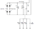
Convert my 2a3 se Srpp JE labs design to run them.
So I will need to replace the filament transformers (so, I need some Hammond 266 series, centre tapped 240v to 6.3v, is this the 3.15-0-3.15 one???)
Also, running Altec a7 VOTT, will the 6a3 filament hum as some people say?
 
The 6A3 will definitely need to have a DC heater supply, regulated or just a rectifier and caps.

A simple circuit would be a 6.3VAC/2.5A secondary (no center tap) > 6A bridge recitifier > 4700uF>0.75 Ohm 3W, resistor > 4700uF this will give you 6.3VDC at the filament. You'll need two circuits such as this, one for each tube.
 
Be sure that the first 4700uF cap is rated for at least 1.5A of ripple current at 120Hz at rated for at least 10VDC.
 
You could also do something similar to the Get*SET*Go DC heaters:

1654116256610.png

It may be overkill for your purposes, but FWIW, this is dead-quiet with 6B4G outputs.
 

Attachments

  • 1654115779964.png
    1654115779964.png
    14.3 KB · Views: 10
Excellent, thanks gentlemen. Overkill is better than underkill. So I will not need a hum cancelling pot, and the transformer does not have to be centre tapped? I have a couple of filament transformers, however they are rated for only 2amps. I guess I can’t use them?
 
2A is the bare minimum I would use for this purpose. 1N5820 diodes would be OK for the bridge. The 0.75 ohm resistor should be rated for at least 3W.
 
Why are R11 and R13 different?
I believe the values were tweaked to minimize 120Hz noise, but I'm having trouble verifying. The old DIYTube site is getting a little creaky.

[EDIT: found the reference!]

"Leave the 51/47 ohm resistors alone. They act like a hum balance pot, and those values work the best in the design."
 
Why are R11 and R13 different?
There is a bit of a difference in current that flows through each resistor because the negative end of the filament eats up a few of the bias volts and draws a hair more current while the positive end does the opposite. Tweaking these resistor values a bit will make the filament voltage more like +/-3V around the center tap. This isn't 100% necessary but resistors are cheap, so why not?
 
There is a bit of a difference in current that flows through each resistor because the negative end of the filament eats up a few of the bias volts and draws a hair more current while the positive end does the opposite. Tweaking these resistor values a bit will make the filament voltage more like +/-3V around the center tap. This isn't 100% necessary but resistors are cheap, so why not?
Thank you for the more thorough answer, Paul. :)
 
The 0.75 ohm resistor should be a 3W rated part. If a 1W part is used, I would expect a year or two of daily use before it gives up.
 
Back
Top