You are using an out of date browser. It may not display this or other websites correctly.
You should upgrade or use an alternative browser.
You should upgrade or use an alternative browser.
3C24 new Build
- Thread starter Wntrmute2
- Start date
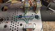
Looking for opinions as how to best dress the heater wiring for the 866A's I am using. The transformer is a 5V and the tubes will be run in series. Twisting the leads doesn't seem to be beneficial as there still will be long sections of non-twisted wire.
The B+ wire also seems to be problematic as well as the wire connecting the two sockets.
A side question would be, how would you deal with three wires that are carrying AC? Twisting them seem that it would lead to asymmetrical cancellation.

The B+ wire also seems to be problematic as well as the wire connecting the two sockets.
A side question would be, how would you deal with three wires that are carrying AC? Twisting them seem that it would lead to asymmetrical cancellation.

I had a long, contentious conversation with someone recently on another forum regarding twisted filament wires. After citing several examples and noting that transmission line theory governs this subject, I was eventually accused of being a bully.Looking for opinions as how to best dress the heater wiring for the 866A's I am using. The transformer is a 5V and the tubes will be run in series. Twisting the leads doesn't seem to be beneficial as there still will be long sections of non-twisted wire.
The B+ wire also seems to be problematic as well as the wire connecting the two sockets.
A side question would be, how would you deal with three wires that are carrying AC? Twisting them seem that it would lead to asymmetrical cancellation.
 I'm not going down that road again, but I'll address the issue of three wires. If it was me, I would just twist or wire-tie them together in a bundle and test it. Route them in such a way that you can add a shield if they cause problems. You can slip a length of tinned braid over them, heatshrink it and ground it. Alternately, you can use a section of shielded 3-wire line cord.
Jack
I wasn't sure if that would be an improvement - braiding the short distance before the need to split to the sockets would be much of a benefit.
Would you just shield the wires individually then and not try to twist/braid/bundle?
Care to share a link to that thread?I had a long, contentious conversation with someone recently on another forum regarding twisted filament wires. After citing several examples and noting that transmission line theory governs this subject, I was eventually accused of being a bully.I'm not going down that road again, but I'll address the issue of three wires. If it was me, I would just twist or wire-tie them together in a bundle and test it. Route them in such a way that you can add a shield if they cause problems. You can slip a length of tinned braid over them, heatshrink it and ground it. Alternately, you can use a section of shielded 3-wire line cord.
Jack
Would you just shield the wires individually then and not try to twist/braid/bundle?
Last edited:
I meant that you could enclose all three wires inside the tinned braid. A shielded 3-wire line cord using 18ga or 16ga would serve the same purpose. This was common practice in some older gear. AC wiring routed to a front panel switch was often enclosed in a flexible metal conduit connected to ground. Bear in mind, I'm not saying that you'll find this necessary. If the run is short and not too close to active circuitry (especially grid wiring), it's probably not worth worrying about.
Looking at the image you posted, I would just keep them down against the chassis and move forward with the project. It's likely this won't be a problem.
The wires are at the opposite end of the chassis from the signal portion. It would be easy to shield all the wires with sleeving I have and ground them to the chassis though.Looking at the image you posted, I would just keep them down against the chassis and move forward with the project. It's likely this won't be a problem.
I think that should work just fine.
I would not bother with the voltage divider. Back when we were working on the 3rd iteration of the SEX amp, I spent some time trying to drive the noise floor of the amp down super low. I tested a transformer CT to audio ground, transformer CT to chassis, resistor CT to audio ground, and resistor CT to chassis, and in that amp at least, the resistor CT to chassis was quite a bit quieter for whatever reason.
Another question. My heater voltage is a bit high 2.7V on the 866 heaters. I read somewhere that I shouldn't put my dropping resistors on the secondary side of the 5V transformer but on the primary side. Through trial and error I found that a 50Ω resistor on the primary will give me the proper reduction. Is this the correct location for this resistor?
TIA
TIA
Some reduction on the primary wouldn't be a problem. Be sure to calculate the dissipation through the resistor and to use an adequately rated part though! I would also suggest carefully probing the pins of the 866s themselves while that PT is energized to see if there's any loss through the socket, and as always use a meter that has a low AC voltage scale (seeing 2.7V on a meter that has a 200V AC scale as the lowest may not be accurate enough to trust).
Provided you pay attention to the real power rating, there's nothing at all wrong with these. In fact in many instances it's much easier to find non-inductive versions of these than anything else!I was going to use a couple of those aluminum bolt down resistors you dislike
Similar threads
- Replies
- 14
- Views
- 729
- Replies
- 9
- Views
- 873


