I am hoping to create a thread for general questions related to DIYing tube gear and associated bits. Topics such as I'm going to post for instance so they don't get buried in someone's thread. Maybe a sticky if it merits.
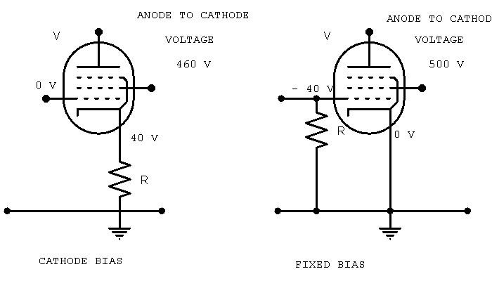
Question # 1) Could someone explain the differences between the different schemes for cathode biasing?
Question #1a) Same question for grid bias?
TIA
Question # 1) Could someone explain the differences between the different schemes for cathode biasing?
Question #1a) Same question for grid bias?
TIA