So, took a long hiatus from the WE KS-6368. The original KS-6368 has a long list of materials, mold tools, and fabrication challenges. Also, by all accounts, it was a dark sounding horn. None the less, the throat-through-mouth design continues to fascinate and stays stuck in my head.
The long break was needed to come up with reasonable solutions the many challenges:
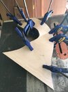
1) Materials. Could not find the right flannel/fabric material that conforms to the extractable mold forms. Laying up wood veneers is a solution. However, the "banking" angles on the sides went the wrong way. Making bending and forming the sides very challenging.
2) How to bend/shape/pre-form the two sides, top and bottom pieces out of wood?
3) How to join the pieces together given the walls will be quite thin (about 0.2-0.25 inches)?
4) Fabricating the thin upright throat out of wood is problematic. Likely will have to be double-sided CNC'ed to get the correct shapes and wall thickness.
5) How to mount a modern 1" CD with very little clearance?
...
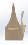
The model below is for an Altec 1" type CD. Mouth is 16" x 16" square. Horn front to back is just shy of 16". Effective horn length is 40".
Cast metal throat going into a bent wood body. Stole the metal throat going into a wooden body idea from the WE 15A! Casting the throat also provides for additional features to secure the top and bottom of the wooden body to the throat - improving overall rigidity. Original KS-6368 uses cloth ribbons and dextrin - not very rigid.

From this angle, the side bank turns with the right side higher than the left side at the end. Having attempted to form the sides of the WE 6368, the bank turns the other way. In effect, you will have to twist the wood counter clockwise while bending it down. The opposite bank turn in this design should minimize the twist on the inside edge. That little bump at the upper right/inside edge is to account for the cross-section area of the upright throat piece to maintain the correct expansion ratio.

The upright throat is slim viewing from the front. Wide viewing from the side. This is to be as least disturbance to sound waves as possible.


The CD is first mounted to a threaded flange. Then, the assembly is screwed into the threaded throat.


This model is a cumulation of months of on-and-off thinking and lessons learned from past attempts. Okay, dammed the torpedoes. Full speed ahead!
The long break was needed to come up with reasonable solutions the many challenges:
1) Materials. Could not find the right flannel/fabric material that conforms to the extractable mold forms. Laying up wood veneers is a solution. However, the "banking" angles on the sides went the wrong way. Making bending and forming the sides very challenging.
2) How to bend/shape/pre-form the two sides, top and bottom pieces out of wood?
3) How to join the pieces together given the walls will be quite thin (about 0.2-0.25 inches)?
4) Fabricating the thin upright throat out of wood is problematic. Likely will have to be double-sided CNC'ed to get the correct shapes and wall thickness.
5) How to mount a modern 1" CD with very little clearance?
...
The model below is for an Altec 1" type CD. Mouth is 16" x 16" square. Horn front to back is just shy of 16". Effective horn length is 40".
Cast metal throat going into a bent wood body. Stole the metal throat going into a wooden body idea from the WE 15A! Casting the throat also provides for additional features to secure the top and bottom of the wooden body to the throat - improving overall rigidity. Original KS-6368 uses cloth ribbons and dextrin - not very rigid.
From this angle, the side bank turns with the right side higher than the left side at the end. Having attempted to form the sides of the WE 6368, the bank turns the other way. In effect, you will have to twist the wood counter clockwise while bending it down. The opposite bank turn in this design should minimize the twist on the inside edge. That little bump at the upper right/inside edge is to account for the cross-section area of the upright throat piece to maintain the correct expansion ratio.
The upright throat is slim viewing from the front. Wide viewing from the side. This is to be as least disturbance to sound waves as possible.
The CD is first mounted to a threaded flange. Then, the assembly is screwed into the threaded throat.
This model is a cumulation of months of on-and-off thinking and lessons learned from past attempts. Okay, dammed the torpedoes. Full speed ahead!
Last edited:


")