You are using an out of date browser. It may not display this or other websites correctly.
You should upgrade or use an alternative browser.
You should upgrade or use an alternative browser.
My first restoration....don't know where to start
- Thread starter djnagle
- Start date
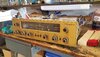


I have done about ten Fisher receivers in the last 5 years. If you want a play by play of how I would do it, post a photo of the top of the unit and the inside of the unit, and I can draw some arrows to stuff I'd pull out and replace.
Be sure you have one of these to start (not the one with the rubber bulb! An acceptable substitute would be one with an electric pump)
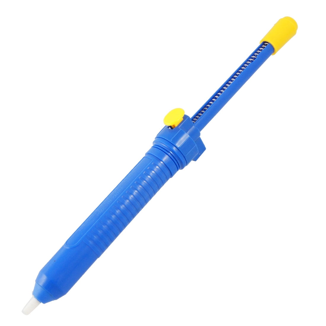
Be sure you have one of these to start (not the one with the rubber bulb! An acceptable substitute would be one with an electric pump)
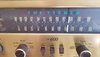
I restored a 500S, which is somewhat similar to the 600. The resistors used in the 500S were carbon film (not carbon comp) - I'm assuming they used the same in your 600 - so I didn't have too much trouble with drifting values. I checked some critical values in the preamp / amp stages for drift, but mostly just recapped all the electrolytics and the coupling caps.Hi All. I got this Fisher 600 from the original owner and it fires up but I'd like to fix it up for a daily driver on my dest top.
I don't listen to FM so not to concerned with that.
This kind of question is way too general to be easily answered. If you need a very non-inductive resistor, then carbon composition resistors are great. If you need something that's pretty quiet when DC current is being drawn through it, carbon composition resistors aren't all that great, and something like carbon film looks like a better choice. Neither resistor type has particularly tight tolerances.So can I assume carbon film is better than carbon comp?
Carbon comps are hygroscopic. They will absorb moisture from the atmosphere. Also tend to up thermal noise in audio.So can I assume carbon film is better than carbon comp?


Naturally you have a serial number that's in the gap where there doesn't appear to be a service manual. I'll just work from the serial numbers just before yours.
First things first, you'll want to put on a 3 wire power cord. You can squeeze the cable clamp with a pair of channel lock pliers, then pull it out. Strip the outside black jacket of a computer power cord, then crimp that gland on right where the stripped off bit starts and put it back in the chassis. I would leave 3-4" of stripped wire at least to work with.
The black wire in the PC power cord needs to go to the fuse holder/power switch feed, the white wire to where the other power cord landed, and the green wire to the chassis. There's a terminal strip right where the power cord comes in that has some ground lugs, I would use one of those.
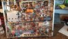
Since you have provided an earth reference, C18 in the schematic can go away. That's the black/yellow cap I've pointed out below.
First things first, you'll want to put on a 3 wire power cord. You can squeeze the cable clamp with a pair of channel lock pliers, then pull it out. Strip the outside black jacket of a computer power cord, then crimp that gland on right where the stripped off bit starts and put it back in the chassis. I would leave 3-4" of stripped wire at least to work with.
The black wire in the PC power cord needs to go to the fuse holder/power switch feed, the white wire to where the other power cord landed, and the green wire to the chassis. There's a terminal strip right where the power cord comes in that has some ground lugs, I would use one of those.
Since you have provided an earth reference, C18 in the schematic can go away. That's the black/yellow cap I've pointed out below.
Attachments
I have a Harman Kardon A300 with a two prong cord, keep telling myself I need to change that out.... Great first suggestion @paulbottlehead .
Cant wait to see this beauty up and running @djnagle , EL84 to boot!
Cant wait to see this beauty up and running @djnagle , EL84 to boot!

It gets great reviews with a great reputation. It will be driving my Lorenz LP312 12" drivers in TL cabs.
View attachment 24100
i heard a pair of Lorenz about a year ago. Very nice sounding speakers. Don’t remember which model they were though... it was very brief. The day I bought my Altec Boleros

The next step will be replacing the first power supply capacitor. In the schematic I was working on, this is called out at C-37 and us a 4 section capacitor that's 40/40/20/20.

So, now you have some choices. If you want to be the most period correct, you would buy something like this to put back in that hole:
CE 4 Section Cap
These are pretty expensive, but they fit the holes perfectly and they require the least modification of the receiver. You have to be really careful that the cap isn't too tall to fit under the cover, so triple check that.
Another option is to remove the old cap and use a standard 1-3/8" multisection cap. You could put a 47uF/47uF F&T cap in there, but that will require you to tuck two 22uF caps under the chassis. For the 22uF caps, I like the Axial F&T electrolytics, as they are easy to fit and have long leads.
The last option is to leave the old cap and tuck all the new caps under the chassis. I have a Fisher 400 receiver that I am consigning for a friend that was done like this. This is my least favorite option, as it's hard to look at the receiver from the outside an know it was recapped, and it looks horrible on the inside.
For whichever option you go with, I would replace all the resistors that go on that cap as well, as getting the old carbon comp resistors off can be tough. This is a good place for Vishay PR-02 and Vishay PR-03 resistors.
If you are going to order that cap from Antique Electronic Supply, you will need two more to complete the job here. You would need:
This one and this one. Just check that they aren't too tall. The four section cap has two 30uF sections that will have to go down to 20uF, which shouldn't present any issues.

Similar threads
- Replies
- 4
- Views
- 534
- Replies
- 0
- Views
- 156