New Worlds Best Phono-Stage

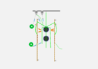
Back to work on my grounding scheme. I'm trying to follow @Salectric sketch but things don't seem to be working out. My valves and caps are roughly where Sal has shown below.
E9C21005-3281-4493-8DB9-8BB396BA4DE4.jpeg

Grounding Phono.png

Can I just attach all the components to the bus between the two big caps? Maybe separate the high power LED connection somehow? The above seems clunky with bus bars hanging out all over.
 
Last edited:
Can you do that? Yes, you can. What is helpful to remember is that the ground buss carries signal currents, so the 5mV or so of voltage that appears from your phono cartridge across the 47K resistor will create a 100nA current in each channel that flows through the ground. If each channel shares the same piece of buss wire, these currents can mix. These AC currents will also flow through those power supply caps, so this all gets rather complicated and when signal are small it tends to matter a bit more than in something like a power amp.

Sal will definitely have some ideas about this, but I would suggest running a ground buss for each channel that goes up to the earth lug and ties to the chassis. Run the B- from you high voltage power supply with its own wire to the earth post as well. I would then use one of your can caps per channel so that the cap ground can be tethered to the appropriate side of the circuit for that channel.
 
I wouldn't put everything together between the caps, personally. I also think that grounding layout looks good.

You might take the grounding leg that the single led terminates to, and move it "down" so that the single led terminates closer to the group of 4. This would change that leg from going up, then down, just to catch the single led. That could clean it up a bit.
 
Thanks @paul_b and @gable.

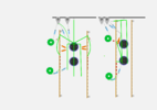
@paul_b , is the schematic on the right what you had in mind?
Two buss bars connected at the ground post and each leg running to one of the two negative terminals of each of the can caps?
Grounding Phono2.png
 
Yes. If you stretch those grounds from the caps to the second to last terminal on your strips, then you'll have a ground buss the whole way down (and your signal output wires can originate at that end).
 
OK, Next issue.
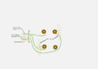
I'm planning on my low voltage regulators (X2) being mounted in the power supply chassis. I want to put some test points for the heater voltage in the audio chassis. Should I measure at Test Points A (red oval) or at Test Points B (orange oval) or does it matter? Pete Millet, who's boards I'm using, recommended splitting the load between two boards.
TIA as usual.
Phono-heaters-test points.png
 
I would skip the test points. You should be able to set the regulators (if they are adjustable and need to be set) with no load, then forget about them pretty much forever.
 
I agree that heater voltage test points are unnecessary. In addition the wiring for the test points can be an antenna for stray RFI.

In my opinion voltage regulators for the heater supply are also unnecessary and in my experience can be detrimental sonically. Despite my feelings, if someone does use regulators I suggest they be in the audio chassis and not the PS chassis. There are two reasons: first, the wiring between the two chassis will definitely have some voltage drop and it’s easier to get the exact voltage you want by adjusting the heater supply inside the audio chassis where the wire losses are much less. Second, and the more important reason, the final filtering for the heater supply should occur close to the tubes in order to reduce the effects of any RFI picked up in the umbilical wiring. When a regulator is used it serves this function so it should be fairly close to the tubes.

My preferred practice is to have just the raw supplies (B+ and heater) in the outboard PS and have all the final filtering in the audio chassis.
 
Thanks Sal. I might change that around but I've cut some pretty big holes in the PS chassis for the heat sinks already.
 
I agree that heater voltage test points are unnecessary. In addition the wiring for the test points can be an antenna for stray RFI.

In my opinion voltage regulators for the heater supply are also unnecessary and in my experience can be detrimental sonically. Despite my feelings, if someone does use regulators I suggest they be in the audio chassis and not the PS chassis. There are two reasons: first, the wiring between the two chassis will definitely have some voltage drop and it’s easier to get the exact voltage you want by adjusting the heater supply inside the audio chassis where the wire losses are much less. Second, and the more important reason, the final filtering for the heater supply should occur close to the tubes in order to reduce the effects of any RFI picked up in the umbilical wiring. When a regulator is used it serves this function so it should be fairly close to the tubes.

My preferred practice is to have just the raw supplies (B+ and heater) in the outboard PS and have all the final filtering in the audio chassis.

What he said ⏫. All of it.
 
Starting new build thread as the other one was getting too lengthy.
So same basic circuit and tubes. Will probably build with metal film resistors and some FT-1 and Miflex coupling caps. Vishays for the RIAA circuit. Searching for some low tolerance caps for that same circuit. I want better than 10% which is what the REL-Caps are.

My first question is will it be acceptable to use a Hammond 193J 10H/200mA/82Ω in the power supply rather than the Hammond 193H 5H/200mA/65Ω that's specified? I get less ripple and about 3-4 less RMS voltage when plugging in those different chokes into PSUD. I happen to have the 193J on the shelf.
Thanks to all that join in!


I was wondering why the very small 0,1uf coupling capacitor. Are you purposely minimizing the bass response
to minimize LP warp problems? Here is a link to a calculator that I have been informed follows Stanley Lipshitz AES
RIAA article.


I was wondering why the very small 0,1uf coupling capacitor. Are you purposely minimizing the bass response
to minimize LP warp problems? Here is a link to a calculator that I have been informed follows Stanley Lipshitz AES
RIAA article.


There's way more at work than the Lipshitz paper mentions. He looks at the EQ network loaded by a huge Z, driven from a source of very low Z. That is not the real world espeically when using valves.

So in the real world with a relatively high drive Z, in this case roughly 2 to 3k (so the EQ loads the driven stage; not metioned in Lipshitz) and all other factors taken into consideration, the EQ values which also include the coupling cap and load Z of the 2nd stage (these are not mentioned in Lipshitz), you arrive in a circuit sim at the values shown. This particular circuit also has an EQ point at 50kHz.

It is nigh on impossible to get the EQ right in a valve circuit with a calculator unless heroic methods are used so a full circuit sim is your best chance
 
I was wondering why the very small 0,1uf coupling capacitor. Are you purposely minimizing the bass response
to minimize LP warp problems? Here is a link to a calculator that I have been informed follows Stanley Lipshitz AES
RIAA article.

The .1uf coupler is loaded with 330K which gives a -3db point of 4.8Hz. That is low enough for full range audio signals.
 
Last edited:
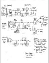
While here, I am wondering about orientation of the outer foil of the capacitors.
I am thinking that for the RIAA caps the outer foil should be oriented towards the ground bus.
While the coupling caps should have their outer foils orientated towards the preceding stages' plate.
Does that seem correct for both the 0.1uf interstage cap as well as the final output cap?

Screenshot 2022-03-26 112908.jpg
 
Izzy: There's way more at work than the Lipshitz paper mentions. He looks at the EQ network loaded by a huge Z, driven from a source of very low Z. That is not the real world espeically when using valves.

Me: That is real world, been done for decades. Check back of RCA Tube Manual, late 50s on as just one example. One will never obtain a truly accurate phono stage compromising the RIAA equalization to fit the rest of the phono circuit. It will always be a compromise.
See more in my reply.

Izzy: So in the real world with a relatively high drive Z, in this case roughly 2 to 3k (so the EQ loads the driven stage; not metioned in Lipshitz) and all other factors taken into consideration, the EQ values which also include the coupling cap and load Z of the 2nd stage (these are not mentioned in Lipshitz), you arrive in a circuit sim at the values shown. This particular circuit also has an EQ point at 50kHz.

Me: Since you mention it, the designs and concepts I have seen everywhere have been backward. To correct the false assumption,
V1, and certainly not overloaded due to the 21k resistor load, ~10 times RL parallel Rp. To substantiate my claim, besides my own actual measurements, the RCA Radiotron Designers Handbook (26 engineers) states 5 times is not an overload. Distortion is not increased. See more below. One will never fulfill maximum sonic accuracy and pleasure if one has to compromise the RIAA network due to the many reactive components involved.

The correct design procedure is to design the RIAA equalization first, and correctly. Then finish properly designing the rest of the circuit, including the power supply to get the circuit and sound right.

Checking further, one sees a 0.1uf coupling capacitor and 330k load resistor. That combo is a multiple problem producer.
First, the load resistor 330k ohm is paralleled by the miller capacitance of the 5687. That capacitance is 4pf times the gain, ~12 plus 4pf from grid to cathode, or 52pf. At 20khz, the load is now only ~105k ohms. The 52pf and 105k is not a huge problem, but all the little things does affect the highs by ~0.3db. The problem is the fall off is not just a 6db/first order, but complex in nature. A 6db/first order fix won’t correct the problem.

The bass is another matter. Due to interactions, at 20hz, the response is off by ~0,8db (using a simulator on hand). But not just a first order/6db rate, but is complex, not linear, so a simple first order/6db fix won’t work. Increasing the 0,1uf by 10 to 30 times should help flatten the bass response.

I won't mention the grid leakage current and its effects.

Izzy: It is nigh on impossible to get the EQ right in a valve circuit with a calculator unless heroic methods are used so a full circuit sim is your best chance.

Me: As a matter of fact, it is possible but not the way you indicate. If one designs the RIAA first, then finish the design for maximum accuracy of the entire phono stage, superior results can be obtained. I have accomplished such and the sound is glorious. But remember, superior accurate parts, layout, connection techniques, physics are involved. It is not just a few equations or simulations.

I hope this helps all involved in understanding, and to accomplish a superior phono stage.

pos
 
Last edited:
@Positron, I beg you to start your own thread regarding your theories. Regarding THIS build, your assertions and references to builds you once again refuse to share serves to only confuse me and chase helpful folks into the weeds.
Please, please cease and desist!
 
Last edited:
@Positron, I beg you to start your own thread regarding your theories. Regarding THIS build, your assertions and references to builds you once again refuse to share serves to only confuse me and chase helpful folks into the weeds.
Please, please cease and desist!
I simply asked a question concerning the lower frequency response, whether designed for warped LPs or other. I had to
respond to Izzy's inaccurate scientific reply.

The Laws I posted, including RCA Radiotron Designers Handbook info, has been understood for 70+ years.
Obviously not theories. :)

I used the exact same laws and procedures in my components. It is simply a matter of starting with the complex RIAA equalization
and going on from there.

Important. With 3 reactive components influencing each other, a complex situation, a simple fix will not
correct the RIAA inaccuracies. One will never reach maximum sonic quality/naturalness.

Please remember that parts quality is important. I was glad to see Izzy list Vishay's, excellent quality parts. Now for coupling
caps, jacks, 6N wire.

Another help is to replace electrolytics (whether black gates or typical electrolytics) with poly capacitors, especially the decoupling
capacitors "next" to the vacuum tubes, connecting to RL of each tube's plate. You will have to investigate which poly caps are the best,
and whether one large or many smaller values in parallel is best. But then again, investigating, R&D, is half the fun.

"THIS build" is titled as "New Worlds Best Phono-Stage", remember....
but how many will falsely believe that it is the worlds best?

If versatility is what one is looking for, this is not bad as rectifiers, power transformer, power cord etc can alter the sound
due to the limited filtering sections (that affect the sonics). Have fun with experimenting.

Have fun with your project and I hope your success.

pos
 
Last edited:
Just wanted to point out that the name of this phono-stage is a bit tongue in cheek.

Additional question. Since I have identified the outer foil on the caps I'm using, I think I should orient the outer foil's lead towards the ground bus in the RIAA circuit and the coupling caps outer foils towards the plate of the preceding amplification stage. IOW, the 0.1 coupling cap's outer foil towards the D3A's plate and the final coupling caps outer foil towards the plate of the 5867 tube. Seem correct?
Thanks
Dave
I thought I posted this question before but I don't see it. Oh well.

I saw the other string and it sounded like you were claiming the absolutely ultimate. Just knew of
some suggestions that would improve the design. Did not mean to confuse anyone.

Yes, I agree, outer foils toward ground or plate of preceding tube. Of course one can see considerable impedance (Z)
no matter which way one looks, but a factor of ~10, give or take lower looking left, at 60 or 120hz, and good to
follow convention unless some extenuating circumstances or error.

Cheers

pos.
 
Last edited:
Back
Top