You are using an out of date browser. It may not display this or other websites correctly.
You should upgrade or use an alternative browser.
You should upgrade or use an alternative browser.
Next Phono-Stage Recommendations
- Thread starter Wntrmute2
- Start date
Just to post a progress with 6SJ7 tubes or better the lack of it.
Tryed every connection and got buzz and some other manifestations.
1 - Pin 1 to chasis - buzz than bang like TT GND was suddenly disconnected.
2 - Pin 1 to signal ground - worked for cca. 3 hours without trouble than buzz developed.
3 - Pin 1 to cathode - no buzz but music greatly attenuated, barely heard on speakers - furthermore measurement with multimeter shows voltages from normal to very high, like the tube is conducting current and in the next instant does no conduct current at all.
4 - Pin 1 - not connected - buzz.
I suspect that Pin 1 should somewhere on the signal ground - just need to find the proper place
( if this doesn't work than i'm at my witts end ).

My build needed the pin 1 connection of the 6SJ7 to the audio ground for best results. Very acceptable noise level. Grounding to the metal chassis wan not acceptable to my suprise!. I thought making the shield part of the Faraday cage would have worked but not so much.
My build needed the pin 1 connection of the 6SJ7 to the audio ground for best results.
Yes i know how You handled that - it was ok at my piece for about 3 hours before the buzz appeared.
Anyway after doing all that Pin 1 connections to various places it seems that possible catasrophic damage occured to all 6SJ7 tubes i have ( 4 pieces ) - when turning on for measuring voltages tonight - 6SL7 & 6SN7 got them alright repeatedly but the 6SJ7's got 300 Vdc on Anodes and 295 Vdc at Cathodes which presently makes no sense to me.
Will try tomorrow, these metal tubes that i have definitelly need more time to properly warm up..... so maybe i measured just too fast although 295 Vdc at Cathodes does not makes any sense to me.
Last edited:
I would expect that if that pin 1 connection was good for hours and then deteriorating, it isn't a problem with where you connected it.
That was / is a suspicion number 2 in my thinking - i assumed tubes because that buzz afterwards was not present in the first minutes after start but only after he 6SJ7's heated properly, after more than five minutes of work - so it seemed to me it was not a construction error since that would be heard much sooner ( at least in my expirience so far ).
Presently i am too tired to think so will resume tomorrow to see what happens with those voltages on the first stages.
Need to see what happens when the tubes warm up ( 6SJ7's ) and from there is it ok or will i rebuilt completely first stages with all elements.
So the things are not so glum - i desoldered all the first stage elements and they are alright - so not dead.
Will replace them with other ones, this was just checking things.
It seems a little clearear what happened - the 6SJ7 tubes will be tested in a few days but i consider them dead.
It looks to me that tubes did not draw any current and that saved the elements but remains to see what was the root cause for killing them and what exactly caused the buzz - bad solder joint or something else.
Upon a more thorough inspection that first stage connection ( Cathode res, bypass cap, G2 res & 0,22 cap, G1 47K5 res ) - to GND bus from both channels was not really good - another mistake in hindsight was using too thick solid core wire, 2,5mm2, for a ground bus - could have done this with half that far more easily.
Last edited:
Finally the phono works.
Had minimaly changed how the psu negative / commons are connected ( linear connection, from minus to minus on capacitors and than to the end of the ground bus over phono circuitry ).
Rebuilded the first stage and finally bought new 6SJ7 tubes.
DC elevaton on the heater supply is slightly lowered, below 80 Vdc because that is the maximum for 6SJ7 tubes, ideally there should be separate DC heater regulator for these tubes with negative side grounded ( datasheet info ).
So far no buzz as before, Pin 1 / Shield not connected anywhere ( this is something i've seen in many builds even if datasheets recommend grounding them for low noise operation ). No hum either.
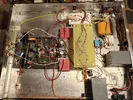
Pics of the inside in a few days, for now just listening the records.
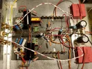
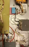
This is what i did for grounding - it is easier to write it up than to see it exactly on the photo :
The PSU is cLC-LC > RC for each channel ( which becomes last stage decoupling caps in single box ).
320-CT-320 / 40 mA PTX > 6X5 > 0,57 uF / 1kV > 30 Hy choke > 100 uF / 800 Vdc kemet > 10 Hy choke > 100 uF / 800 Vdc Kemet cap. Last RC is at the back of phono circuitry, 1K > 47 uF / 450 Vdc Rubycon radial Elco for each channel.
Capacitors in the PSU are Kemet C4 DC-Link four pin type - these are not Celvin connection type, so far as i know pair of pins are internally connected together. First i connected them externally also for easier wiring, both plus pins and minus pins.
The plus pins remaind connected but connection was cut off at the minus side.
So when routing wires from cap to cap i used first minus pin as "input" and second pin as "output", from the second cap to the ground bus end over phono circuitry.
There at the end of the ground bus were also connected 47 uf / 450 Vdc caps for CF stage decoupling.
Overall for every phono stage i did the following : 47K grid shunt res, Rk + Ck, G2 decoupling cap all go the one point formed from Rk + Ck and than to ground bus. First stage 47 uF / 450 Vdc F&T axial cap is next on the ground bus.
RIAA EQ is part that forms second stage Rg, Rk + Ck one point and then to ground bus.
Same goes for 6SN7 cathode follower, just Rk to ground bus and after it comes the last stage 47uF / 450 Vdc decoupling and PSU Common / Minus side at the end.
Ground bus begins at the isolated turntable ground connector ( RCA minus from inputs are first connections on it ).
Chasis connection is made at the turntable ground post via long wire, 10R NTC resistor and then the chasis ( the wire should be short ).
Within a few days will post pictures of the insides and the schematics.
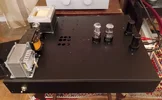
Here are the pics. Made one mistake in description :
Second 100 uF / 800 Vdc Kemet capacitor has minus connection only on one pin, incoming & outgoing towards the bus bur.
Anyway not the best i could do but decent enough to work correctly on high efficient speakers.
My first work with tube rectifier and chokes - I'm sold to that option - it is ideal to put before regulator, if used, in my limited experience, also better than multiple RC sections.
Sound of mine unit currently with very strong low frequency range, no capacitor at the input which will be tried in following days since i use Shure V15/3 for a cart.
Capacitors in the PSU are Kemet C4 DC-Link four pin type - these are not Celvin connection type, so far as i know pair of pins are internally connected together. First i connected them externally also for easier wiring, both plus pins and minus pins.
The plus pins remaind connected but connection was cut off at the minus side.
So when routing wires from cap to cap i used first minus pin as "input" and second pin as "output", from the second cap to the ground bus end over phono circuitry.
Second 100 uF / 800 Vdc Kemet capacitor has minus connection only on one pin, incoming & outgoing towards the bus bur.
Anyway not the best i could do but decent enough to work correctly on high efficient speakers.
My first work with tube rectifier and chokes - I'm sold to that option - it is ideal to put before regulator, if used, in my limited experience, also better than multiple RC sections.
Sound of mine unit currently with very strong low frequency range, no capacitor at the input which will be tried in following days since i use Shure V15/3 for a cart.