You are using an out of date browser. It may not display this or other websites correctly.
You should upgrade or use an alternative browser.
You should upgrade or use an alternative browser.
Pre-Amp Build
- Thread starter Wntrmute2
- Start date
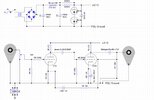
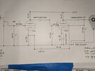
Higher B+ will allow you to use a higher impedance plate loading resistor. This will increase the circuit's open loop gain and decrease distortion a little bit. With 210V of B+, the plate loading resistors could go from 33K to anything between 47K and 53K and you'll end up with about the same cathode bias voltage. Power dissipated through those resistors will rise a bit, so a 47K/5W resistor would be my choice.
I've been waiting patiently for Paul B. to suggest putting a CCS on the plate/cathode of the 76 tubes. I was sure that was one of his planned mods. Since you're now contemplating bigger loading resistors, why not try CCS? I'm no help there, but I'm sure Paul knows the necessary component values off the top of his head.
cheers, Derek
cheers, Derek
Last edited:
In revisiting my calculations and @paulbottlehead's recommendations, I think I need higher wattage resistors than I used. Metal film resistors in 47K @ 5W are impossible to find. I can easily source Mills wirewounds in 5W as well as 12W but I believe I received advise to use the metal film resistors. I can parallel 3W 100K and 91K resistors to come up with approximately 47K. The watts needed to be dissipated by the plate resistors is about 3.5W.
Input?
Input?
I am not sure I need that much power capability. I redid my calculations and came up with about 0.3W.
Voltage drop 120V
Resistor value 47K
I can source Mills 5Watters easily enough. What do you think about non-inductive wire wound resistors or metal oxide?
Voltage drop 120V
Resistor value 47K
I can source Mills 5Watters easily enough. What do you think about non-inductive wire wound resistors or metal oxide?
I'm building another of Paul's masterpieces to replace my George Wright little preamp. It will be like the first but with switchable B+ (I hope).
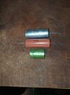
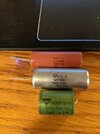
I'd also like to put in a second set of output jacks as I'd like the ability to run a sub-woofer or even just to try a different set of output capacitor flavor. Can I just wire the second set of RCAs in parallel?

I'd also like to put in a second set of output jacks as I'd like the ability to run a sub-woofer or even just to try a different set of output capacitor flavor. Can I just wire the second set of RCAs in parallel?

Similar threads
- Replies
- 32
- Views
- 2K


