This is how I build amplifiers.

Of course I am not intentionally demeaning anyone. What gave you that idea? Nothing could be further from my mind. I’m just explaining how I like to do things. I’m a he, by the way. My given name is Bo. This is a male name that has been around in Sweden at least since the middle ages. The grounding is explained in the first post of this thread. It was moved here from another thread.
Thanks for sharing your name Bo. Mine is Raymond.

My thinking regarding what people can find demeaning - I mean that in the sense of taking away meaning form someone’s efforts - is explained in my post. That term was probably a bit strong. See, the challenges of communication.

I saw reference to the grounding scheme in this thread but not enough explanation for me to understand it. I’m a novice. No problem if there is not more info available.

Cheers.
I find this demeaning idea very peculiar. Experimentation and sharing is what DIY is all about. If this offends your sensibilities, so be it. Actually, I started this thread at the prompting of administrator Marantzfan, who apparently thought that a post I made in another thread had enough merit to stand on its own two legs. That is now post # 1 in this thread.

I don’t claim to be an original thinker, very far from it. I’m more like a sponge, soaking up ideas available to anybody interested in DIY audio. Those I find particularly interesting I try to put into practice. This doesn’t mean that I consider my builds superior to everybody elses. I’m not Jeff Medwin in disguise. There are many ways to skin a cat and mine is one of them.

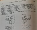
There is nothing particularly complicated about my grounding arrangements. The HT power supply is floating in the PS chassis and is grounded in the audio chassis (all my builds are on two chasses). Exactly where depends on the audio circuit. Left and right audio channels are on separate buses grounded close to the input connectors. In the power amp i’m building at the moment there are only four resistors to ground in each channel. They are the driver tube cathode resistor, the output tube cathode resistor, the driver grid bypass resistor and the output grid bypass resistor. The grid bypassing idea is from the Western Electric repeater amplifier (see Lynn Olsons ETF 2004 presentation). It is also described in The Rosetta Stona article on Lynn Olsons Nutshell Hifi website. The calcs are on page 538 in RDH4.
 
Thanks for sharing more about you grounding schemes - it helps my understanding.

I don’t know what more I can add regarding sharing. I’m not at all offended. I’m all for DIYers sharing and learning… and creating the conditions for that. One point I was trying to make was that communication can be difficult. I shared my personal preferences, and what I think underpins a lot of peoples’ feelings and reactions.

The irony - or possibly a good example - is that maybe I did not communicate that well enough and have contributed to the problem rather than the solution. But maybe I take too much ownership of that. I just wanted to share and help.
 
Last edited:
The HT power supply is floating in the PS chassis and is grounded in the audio chassis (all my builds are on two chasses).
This is also the strategy I use.

The grid biasing arrangement on 538 of RDH4 definitely has some drawbacks but is certainly an interesting arrangement.
 
I’d be interested to learn what these drawback are.
They depend a little on whether you're using it for a driver stage or an output stage. The drawback for both cases shown is that you either need a transformer preceding the tube or a negative rail.

Presuming that you are using this with an interstage transformer in a single ended amplifier, you will lose the benefit of the low DCR of the interstage transformer secondary keeping the output tube grid stable when you push the amp hard. Depending on the values of components being used, you could also be facing far lower input impedance for that stage as well.
Interesting. I use it with an input transformer (driver stage) and an interstage transformer (output stage) in a single ended amplifier. I don’t consider that a drawback, since these transformers are very high quality, Lundahl LL7903 and Monolith respectively. I thought that the high value resistor from the cold end of the transformer secondary to ground would not affect the grid input impedance since it is outside the current loop? Did I get that wrong?
 
With the LL7903 at the input of your amplifier, you're now needing a low source to drive that properly. I would guess that you're using this as a mild step-up so you can use a DHT driver of some sort?
 
With the LL7903 at the input of your amplifier, you're now needing a low source to drive that properly. I would guess that you're using this as a mild step-up so you can use a DHT driver of some sort?
My line amp, (single stage Marconi Osram LP2 in filament bias) has an LL 1660 output transformer in 4,5:1. The output impedance is a couple of hundred Ohms. The AVC tacked on to the output makes the impedance even lower, depending on the setting of the volume control, of course. I use the LL7901 (not the 7903 as I wrote in my previous post) in 1:1. I don’t need step up for the 10Y driver tube into the Siemens F2a output since the F2a is very easy to drive. I have it biased at 12 V.
 
For those who don't have or want to look up page 538 of the RDH4 (Radio Designers Handbook Volume 4)
 

Attachments

  • Page 538 RDH4.jpg
    Page 538 RDH4.jpg
    160 KB · Views: 78
What I called a Graetz bridge transformer is a transformer with half the windings of a CT transformer, requiring a Greatz bridge rectifier to function properly. I make a distinction between ”outdated technology” and ”old technology”. I use old technology all the time, where appropriate. However, there are no old technology phono amps worth considering. Mine is a D3a LCR of my own design. My line amp on the other hand uses a DHT from the 1920s, a Marconi Osram LP2. I use it in filament bias into a Lundahl 1660 line output transformer in 4.5:1 into a Tribute autoformer volume control. In my opinion this is as good as it gets. The lowest possible parts count and no super expensive resistors and capacitors in sight. The plate voltage is set with a voltage regulator tube, the English Electric globe S130P/CV45. I mostly use European voltage regulators since there is a much greater variety in voltages and currents here than what's available in America.

The power amp that I am working on at the moment is based on the Western Electric repeater amplifier (Google Lynn Olsons 2004 ETF presentation). The object is the shortest possible current loops. In fact the whole amplifier is floating above ground, except for the output transformer secondary that is grounded for safety reasons. I’m building this amp also to test the theory that the driver tube is more important than the output tube. The driver in this case is the 10y and the output the Siemens F2a triode coupled that I have used previously in other amps. The output transformer is a parafeed Tribute amorphous core. The plate choke is a nickel dressed Electra Print. The power supply of course is just as important as the signal circuit. The power transformer should have a current capacity at least three times the current draw of the amplifier. The HT filter must be choke input LCLC. Filter capacitors 4 pin DC-link in Kelvin connection, bypassed with GTO caps. It was actually Jeff Medwin who made me aware of the ”hockey puck" GTO caps. I don’t agree with Jeff very often, but I am grateful to him for this info. They sharpen up the leading edge of transients like nothing else. These days I use them everywhere in power supplies and in loudspeaker crossovers.

To make the power amp float above ground an input transformer is necessary. In fact I use input transformers in all my amps. In the phono amp the input transformer is the step up from the LOMC (LL1933ag). In line and power amps I use Lundahl LL7901, LL7903 and LL1674 as appropriate. I live 50 miles from the Lundahl transformer factory, which makes Lundahl trsnsformers an obvious choise.

With input and output transformers there is no excuse for not using balanced interconnects. I use them from tonearm output to power amp input. With balanced ICs the difference between good quality cables from different manufacturers is minimal. This makes cable swapping a thing of the past. Use a good quality, well shielded cable and you’re set for life. I use mostly Gotham cable from Switzerland, cheap but very high quality. Of course, with commercial amplifiers an XLR input or output connector doesn’t guarantee anything. It may be single ended, pseudo balanced or balanced with the well known pin one problem. The pin one problem means that the IC shield is connected straight into audio ground instead of the metal chassis close to the input connector as it should be. The result is that all the crud on the shield goes straight into the signal circuit. This is apparently a very common problem even among reputable manufacturers who should know better.

My loudspeakers also have their origin in the 1940s. They are modeled on the famous Jean Hiraga Altec VOTT A5s. I’m not quite there yet, but i’m getting close. I built them in 1988 and have upgraded and modified them over the years. Pano(maniac) of DIY Audio and Altec Users Board who helped Jean Hiraga rebuild the A5s in 1986 has stated that they are the best speakers he ever heard.

It always helps to understand another's goal, or one's goal. I was wondering what your goal is, accuracy or another goal. By accuracy
I mean if an instrument sounds like the real thing; not the old SS explanation that turns out to be sterile and
non envolving, based on specs only.

Cheers

pos
 
Last edited:
It always helps to understand another's goal, or one's goal. I was wondering what your goal is, accuracy or another goal. By accuracy
I mean if an instrument sounds like the real thing; not the old SS explanation that turns out to be sterile and
non envolving, based on specs only.

Cheers

pos
My (unattainable) goal is a sound that is as close to natural and lifelike as possible. At this time I want to try something more adventurous and exciting (to me) than the usual IDHT RC-coupled to a 300B/2A3. I do realise that such an amp can sound very good, if properly implemented. Been there, done that. Now I’m on a different tack.

For various reasons I haven’t been able to complete the amp yet. One problem is the difficulty in finding a suitable HT power transformer in Europe at present (Covid 19, war in Ukraine etc). Winders I have used for custom PT:s in the past, like Roehrentechnik, Ask Jan First and Sowter, can’t deliver. However I have now found an industrial transformer that seems suitable. It’s a Block FST 160/23 400v/230V pri. 230V sec. I’ll use it back to front of course, 230V pri. 400V sec. It’s available from Conrad in Germany with free shipping. Hopefully the amp will be completed this summer.
Try Monolith Magnetics in Belgium. They were very accommodating when I inquired about a custom PT
 
Try Monolith Magnetics in Belgium. They were very accommodating when I inquired about a custom PT
Yes, Monolith is good. I have Monolith IT:s (for this project) and Monolith Summit OPT:s (for my next, and probably last, stereo amp). I even have a Monolith power transformer in my line amp, but I wanted something a bit less spendy for this project. The parts will still come in at something between 2,5K and 3K USD. I’m retired so I will have to keep some control over the spending.
 
Off topic, but as a resident hifi young(er?) Person, I feel it's my duty to suggest that YouTube is a fine resource for discovering what rap battle looks like.

Enjoying this read, and I've been curious about fully balanced systems for a long time
 
Last edited:
Off topic, but as a resident hifi young(er?) Person, I feel it's my duty to suggest that YouTube is a fine resource for discovering what's rap battle looks like.

Enjoying this read, and I've been curious about fully balanced systems for a long time
I’m sorry, but I’m to old to be interested in rap battles.

I would STRONGLY suggest that you delve deeper into the subject of balanced operation. This is clearly better than single ended interconnects, even in single ended amplifiers. Of course the connections have to be properly balanced according to the AES 48 standard. This is apparently rare in so called ”High End” equipment. An XLR connector on the back of your amplfiier is no guarantee of anything. If you build your own amps you have control, if not, you can’t be sure of anything. The connection may be single ended, pseudo balanced, or balanced with the well known and very common pin 1 problem. Atmasphere is the only manufacturer that I know of that does this right. If you go balanced you don’t have to worry about interconnects any longer. There will be very little difference between different interconnects. Get a good quality, well shielded interconnect from Mogami, Canare, Belden or Gotham and you can stop worrying about interconnects. You’ll save a lot of money, time and effort this way. To begin with Google ”An Overview of Audio System Grounding and Interfacing" by Bill Whitlock of Jensen tranformers. There are also a lot of posts by Ralph Karsten of Atmasphere on this subject on Audiogon Discussion Forum. If you really want to dig into this subject get a copy of ”Grounding and Shielding Techniques” by Ralph Morrison.
 
I would suggest starting with why balanced transmission lines were created in the first place, how they were developed, then where they were used. This will give you some foundation to determining how applicable this may be to a home stereo.

Interconnects still matter. Source impedances and cable capacitances still interact. Why you'd need strong shielding for balanced transmission is something I'd like to hear more about.

The Jensen Transformers website has lots of good reading. I reference it frequently when people try to say that "balanced" refers to equal/opposite signals in an interconnect.
Paul, as you well know balanced transmission lines were developed for long distance telephone transmission in the early decades of the twentieth century. The object was of course to suppress noise as much as possible. Shielding was not used. The sound was adequate for voice transmission but no more than that. For home stereo not good enough.

Balanced refers to equal impedances to ground, nothing else.

Source impedance and cable capacitance is very important for LOMC phono cables, for line level not so much, if you run balanced cables.

I agree that the Jensen Transformers website has lots of good reading, so has the Rane website.
 
The source impedance of a LOMC cartridge is incredibly low, sometimes an order of magnitude (or two) lower than source impedance for line level sources.
 
Hi Boli46,

I asked about your goals because it seems virtually none like natural sounding voices and
instruments. I think you are in the minority, but so am I.

As a general info, balanced is only good to around -40db, and even if better new, say -60db, will
deteriorate with time. I never design around "balanced" for high quality stereo. True balance also costs.

For very long runs, one could minimize 60hz hum by low output impedance (Z) methods.

cheers and hope this helps.

pos
 
Last edited:
Back
Top