You are using an out of date browser. It may not display this or other websites correctly.
You should upgrade or use an alternative browser.
You should upgrade or use an alternative browser.
Western Electric KS12027
- Thread starter Tsingtao_1903
- Start date
Das Bild der Vott habe ich aus dem WWW zusammengebaut. Real sieht die Kiste so aus.
Wenn das KS12027 im oberen Brett eingebaut wird und ein passender Tisch angefertigt wird, sollte die Höhe gut einstellbar sein.
Die BR Öffnung besteht aus 3 Bretter, die geschraubt sind. Innenliegend ist das Brett schwarz und kaum zu erkennen. Das "Krummhorn" oben drauf zu setzen ist aber auch kein Problem.
.jpg")
Wenn das KS12027 im oberen Brett eingebaut wird und ein passender Tisch angefertigt wird, sollte die Höhe gut einstellbar sein.
Die BR Öffnung besteht aus 3 Bretter, die geschraubt sind. Innenliegend ist das Brett schwarz und kaum zu erkennen. Das "Krummhorn" oben drauf zu setzen ist aber auch kein Problem.
ich bin gerade dabei, die Zeichnungen von Tsingtao_1903 nachzuzeichen. Meinen allergrößten Respekt dafür. Das, was ich hier für mich "verbrechen" möchte, kann nur so ähnlich ausschauen wie das KS12027. Der Schwung am Hornhals ist so für mich nicht baubar.
Das Horn als solches ist schon eine kleine Herausforderung, die man aber recht gut bewältigen kann.
Ich probiere das Radialhorn aus gewässerten HDF, dass ich über eine Matritze biege, in Form zu bringen. Das sollte der einfache Teil sein?
Der Hornhals selber wird etwas vernünftiger werden, denke ich mir mal?
Meine Ideen gehen eher auf das "einfache" Nachbauen zurück. Hier möchte ich mich erst einmal bei Tsingtao-1903 herzlich bedanken.
Ich baue das Radialhorn auf 120cm Kogeldurchmesserwas in etwa 47,24" entspricht. Später werde ich es genauer nachrechen, wenn nötig.
Horndaten sind gegeben. Länge , Hornmund und Treiberdurchmesser
Hornmund: 265 cm² ca.590 Hz
Hornlänge: ca. 32,5 cm ca 330 Hz
Hornhals habe ich auf 1" gerechnet.
800Hz sollten da locker drin sein.
Hornlänge ( Hornkonstante * 1,8 (empirisch ermittelt) plus Zugabe
Auch die Kaspie-Theorie. Die Praxis überrascht aber immer wieder ;-)
Gruß aus old Germany, nahe Wuppertal. Die haben damals die Straßenban aufgehängt (zu Kaisers Zeiten) . Sie fährt immer noch
✌
I went to google. This is what the end result was. "I'm in the process of tracing the drawings by Tsingtao_1903. My greatest respect for it. What I would like to "crime" for myself here can only look something like the KS12027. The swing on the horn neck is not buildable for me. The horn as such is a bit of a challenge, but one that can be overcome quite well. I try to shape the radial horn made of watered HDF that I bend over a die. Should that be the easy part? The horn neck itself will be a little more sensible, I guess? My ideas go back to the "simple" reconstruction. First of all, I would like to thank Tsingtao-1903. I build the radial horn to a diameter of 120cm, which corresponds to about 47.24 ". Later I will do more detailed calculations if necessary. Horn dates are given. Length, horn mouth and driver diameter Horn mouth: 265 cm² about 590 Hz Horn length: approx. 32.5 cm approx. 330 Hz I calculated Hornhals to be 1 ". 800Hz should be in there easily. Horn length (horn constant * 1.8 (empirically determined) plus allowance Also the Kaspie theory. The practice surprises again and again ;-) Greetings from old Germany, near Wuppertal. At that time they hung up the street ban (in the emperor's time). She's still driving"
Klasse.
"verbrechen" ist ein Wort von mir, wenn ich irgend etwas nachbauen möchte, wo ich keinen Plan für habe. Die Erbauer würden mir meine Nachbauten "um die Ohrenhauen":mit den Augen rollen:
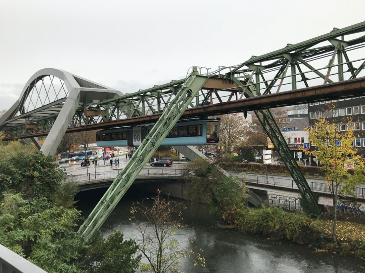
"Schwebebahn"
"verbrechen" ist ein Wort von mir, wenn ich irgend etwas nachbauen möchte, wo ich keinen Plan für habe. Die Erbauer würden mir meine Nachbauten "um die Ohrenhauen":mit den Augen rollen:
"Schwebebahn"
Attachments

I'm not really sure what you are getting at here.Great.
"Crime" is a word of mine when I want to recreate something that I have no plan for. The builders would knock my replicas "around the ears": roll their eyes:
"Suspension railway" View attachment 41681
Taking a stab at this.
The poster is from "Greetings from old Germany, near Wuppertal"
From Wikipedia: The Wuppertal Schewbebahn original name is Einschienige Hängebahn System Eugen Langen (Eugen Langen Monorail Overhead Conveyor System). It is the oldest electric elevated railway with hanging cars in the world and is a unique system in Germany. Designed by Eugen Langen and offered first to the cities of Berlin, Munich and Breslau who all turned it down, the installation with elevated stations was built in Barmen, Elberfeld and Vohwinkel between 1897 and 1903; the first track opened in 1901. The railway line is credited with growth of the original cities and their eventual merger into Wuppertal. The Schwebebahn is still in use as a normal means of local public transport, moving 25 million passengers annually, per the 2008 annual report.
The idea for the Wuppertal suspension railway was turned down initially. But, it prevailed and is still in operation since 1901. Just because an idea is unconventional, don't knock it.
Last edited:
Taking two very different and unrelated concepts and coming up with something that works.
Found a nice article on the "Schwebebahn".
 www.bloomberg.com
With Trains Like Schwebebahn, No Wonder Germans Love Public Transit
Infrastructure like this makes it clear why Germany continues to produce enthusiasm for public transit, generation after generation.
www.bloomberg.com
I use SolidWorks. Can send the files to you if you'd like. If you can only use dxf files, give me a few days. Rather busy at the moment. Will create and send you the files by this weekend.I am going to build a dxf cad file of the Ks-12027. Can you share your file with me?
Hello David,I am going to build a dxf cad file of the Ks-12027.
For clarification. My files are of my own creation based on the external measurements and design features of the Western Electric KS-12027. The original KS-12027 is for 0.7" drivers. My version is for 1.0" drivers. If you want the file for the KS-12027, I don't have it. I call my version WP-12027 to differentiate from the original Western Electric KS-12027. In the old days, WP specs are used by Western Electric Whippany Procurement facility. These Whippany Procurement specs are called "WP" specs for external products where Western Electric did not have ownership of IP properties. However, WE did have engineering change controls and approvals.
Enough of the history lesson. If you still want the dwg for my WP-12027, PM me with your email address. I'll send the file to you. You will still have to create the solid file yourself.
Best regards,
Trieu
One of my rules of engineering: If it's together, break it up in pieces; If it is in pieces, put it all together.this horn could be made unless more than 3 axis CNC is used.
This horn can be machined on a 3 axis CNC in pieces, flipped over to machine the other side and in sections. The difficulty is to align and glue up the pieces, AND to ensure that the joineries and the wood grains are all oriented correctly to support the weight of the drivers.
Not a project I would take on......


Similar threads
- Replies
- 51
- Views
- 6K