Dynaco ST-70 Project

Hi @asilker. Okay, here is a first installment of an answer to your question. :)

While the ST-70 sounded good to my ears and I think I could be happy with it as my only amp, I found that I preferred the sound of my Dynaco SCA-35 and First Watt J2 in my system (driving Meadowlark Swifts). To my ears, the main difference I notice with my ST-70 relative to the other two amps is in the reproduction of vocals and acoustic instruments. The ST-70 is just a little less convincing and transparent. I cannot pinpoint that further at the moment, but I think my impression probably results from a collection of minor differences (imaging seems a little less precise, tonality variances in the midrange, etc).

The output levels produced with the lower power of the SCA-35 and J2 are sufficient for my needs and I don’t believe I am playing the ST-70 any louder. So, its benefit of higher output power is probably going to waste on me with my current system.

Along those lines, I recently rewired the ST-70 output stage tubes in triode mode (disconnected the UL feedback and tied that screen grid pin to the anode via a low value resistor). Although that reduces the maximum output power, the reduced output power is on par with my other amps. I read about this change in various articles and threads I came across on the internet. They are easy to find via search engine, but just let me know if anyone needs links. Some recommend using the next lowest output tap (4 Ohm tap for speakers that are 8 Ohms nominal, etc) in conjunction with this change. And some also recommend disconnecting global feedback. I have been trialing those revisions as well. Disconnecting the feedback was too far in that direction for me, so I have been trialing varying degrees of reduced feedback instead. It does seem there is probably a good compromise somewhere on the spectrum of reduced feedback. There are a number of permutations possible with these variables and I am in no rush to work through them all, so it may be some time before I settle on a particular configuration. And it is also too early for me to say much about resultant subjective quality, but I can at least say that my ears are telling me this is improving those areas where I felt my ST-70 fell a little short of my other two amps.
Hey buddy thanks for the writeup :) this is sort of what I was expecting. I am very eager to hear the st 35 style power stage in my rig. Mine is torn down, I need to straighten out (literally) some chassis problems. I am going to try and really chase down the noise floor for an el84 amp, although I am learning and mostly using other people's circuits. I have a deal for a stereo 70 set up too, and I've been looking at permutations of the Mullard 5-20 format but I just can't find an implementation I'm excited about. This helps confirm my suspicious, at least for the time being

I would love to spend some time with a J2 - wonderful choice in amplification you've got there. Although I do wish you folks would stop buying them so the schematic would go open source 🫠
 
Very interesting report.
I have a tubes 4 hifi octal board waiting for to be built and try in my ST70.
I hope to get to it after the holidays.
That octal driver board looks pretty interesting. Sounds like a fun project for after the holidays. I would be interested to hear about how that goes. I am happy with the driver board I have now, but will probably eventually want to experiment with other options as well. Not any time soon - I need to quit procrastinating and switch gears back to the minor kitchen renovation project (motivation has faded a bit since the kitchen is mostly functional now, and the remaining work is mostly cosmetic). :)

You did a great job restoring my old ST-70! I am very pleased it found a good home and an owner with the patience to do a proper rebuild. I am quite sure that if I hadn’t sold it the parts would still be sitting in storage.
Thank you! I am very appreciative that you offered this project to the forum at a great price and that I was fortunate enough to be the one to claim it. For awhile there, it seemed like I was never going to get to it; but finally, life let up a little and I have been able to get through some of my backlog of projects - audio and otherwise.

Also, interesting comments. When I was deciding which tube amp to build as a first project I kept seeing too many contrasts between EL84 amps and EL34 w/ a clear preference to enhanced mid-range vocals for the EL84 to consider it just a passing opinion set. While I'm only comparing my ST-35 w/ an early Mac SS and old Halfer, I find it highly satisfying in the female vocals and piano jazz material.
Re: your last thought, I feel the same about my SCA-35. I also feel it also sounds very good with male vocals. For example, I had my system playing in the background recently and had to drop what I was doing to give the system my full attention when Lightnin' Hopkins came up in my random play queue. Vocals and guitar sounded so good to my ears. Chills.

What a beautiful build. I'm not the world's biggest ST70 fan, but that one impresses the heck out of me. Nicely done! 👍
Thank you! Really appreciate the positive feedback. I have had some past experience with solid state projects (audio and otherwise), but I have pretty limited experience with vacuum tube projects. I have really enjoyed these Dynaco projects and happy that I was finally able to give them the attention they deserved.

Hey buddy thanks for the writeup :) this is sort of what I was expecting. I am very eager to hear the st 35 style power stage in my rig. Mine is torn down, I need to straighten out (literally) some chassis problems. I am going to try and really chase down the noise floor for an el84 amp, although I am learning and mostly using other people's circuits. I have a deal for a stereo 70 set up too, and I've been looking at permutations of the Mullard 5-20 format but I just can't find an implementation I'm excited about. This helps confirm my suspicious, at least for the time being

I would love to spend some time with a J2 - wonderful choice in amplification you've got there. Although I do wish you folks would stop buying them so the schematic would go open source 🫠
Well, if you ever plan to be in the Austin, TX area while I still own my J2, hit me up and you can hear how one sounds with Meadowlark Swifts. And sorry about my contribution to the demand for them. :) In my opinion though, that demand is well earned. And that amp was certainly a splurge for me. Easily, my most expensive audio purchase (and I bought it used, roughly half the price of new). But I feel it was a great deal in terms of subjective quality obtained from a prebuilt commercial amplifier. Happy I was able to have the J2 in my life for awhile.
 
Last edited:
Swift, I was just being facetious -- I'm convinced the J2 is worth every penny. I appreciate the offer. If I find myself southbound I might take you up on that!
 
I have been enjoying listening to this amp with the output stage wired for triode operation and experimenting with some of the details (amount of global feedback, where that feeds from, output taps). Lots more to learn and explore, but I have heard enough to decide that this change will stick for the time being. So I have updated the wiring accordingly (had some temporary things going on for the early trials)…

53365086043_e0c16d7a9d_k.jpg

Also shown in the image: I had included a thermistor in line with the transformer primary because I was considering moving to solid-state rectification when I put the amp back together. I ultimately decided to stick with the tube rectification and revisited this. Removed the large thermistor on the primary side of the transformer and added a smaller one (about 10 Ohms at room temp) between the rectifier and caps to still provide a little bit of inrush current limiting with the modern caps (while having less impact once it warms up). Also added protection diodes for the rectifier.

So far, somewhere in the realm of 10-13 dB global negative feedback seems to be a good balance of compromises, in my book. One of those is increased hum, which is in the neighborhood of my SCA-35 with that amount of feedback reduction.

Although I have been experimenting with where the R leg of the global feedback feeds from (OT 16 vs 8 vs 4 Ohm tap) and the actual R value, I have not yet experimented much with the global feedback C compensation leg. The rewiring prescribed by all the directions I have found so far result in an increase in the voltage being fed back through that C leg (UL tap vs full output). That may work out well (or at least well enough) with the reduced bandwidth of operating in triode mode (I have no idea at the moment), but I wonder if there is room to reduce or remove the compensation (especially with the reduced feedback). All I have trialled so far is simply moving the C feedback leg to the now otherwise unused UL tap, which increased the upper cut-off frequency a bit without any obvious signs of problems. I haven’t looked at phase response yet, but that is what I plan to explore next. I’ll share more details when I get there.

I trialled my 8 Ohm nominal speakers on the next output tap down as some suggest (4 Ohm tap in my case). That results in a bit of reduction in gain (~2ish dB) and bandwidth (amount varies with NFB / compensation details). Beyond that, any other differences were subtle to my ears and it will take a lot more listening time and content for me to decide whether or not that is an improvement. So, I decided to revisit that later and continue using the 8 Ohm tap for now. I am early in the learning curve on vacuum tube amplifier design, but I *think* one impact of connecting the speakers to the next lowest tap in this particular case is that the output stage will operate in Class A for an additional couple Watts or so if the original bias point is maintained (which is the only recommendation I have seen in conjunction with any of these changes so far). And maximum output power is reduced by a similar amount. Please feel free to correct me if anyone knows or believes otherwise. :)
 
Last edited:
If you are using a 5AR4 rectifier, it is a thermistor.

The open loop gain of the ST-70 with triode strapped outputs drops so substantially that you could probably do without the compensation (the R and C from plate to ground on the first stage). If you end up removing the feedback entirely, it would also likely make some sense to triode strap the first stage to bump open loop gain down a bit, but I think there's a rather substantial risk of having too much noise at the speaker jacks if you completely disable the feedback loop.
 
If you are using a 5AR4 rectifier, it is a thermistor.
I am indeed using a 5AR4 rectifier. So it sounds like there is no real need or benefit with an additional thermistor in that scenario. I was erring on the side of a little extra caution due to the cap board upgrade and me still being early in the learning curve with vacuum tubes. If it isn't needed, I would certainly prefer to remove it altogether. Thanks!

The open loop gain of the ST-70 with triode strapped outputs drops so substantially that you could probably do without the compensation (the R and C from plate to ground on the first stage). If you end up removing the feedback entirely, it would also likely make some sense to triode strap the first stage to bump open loop gain down a bit, but I think there's a rather substantial risk of having too much noise at the speaker jacks if you completely disable the feedback loop.
And thank you for the suggestions regarding the first stage triode strapping and RC compensation. I will explore those as well.

I did listen to the amp with the global feedback disconnected and no other changes (aside from the output stage triode strapping) and the hum and noise increased to the point of being objectionable, at least for my preferences. I don't know how the triode strapping of the first stage will impact that, but if it yields a similar signal to noise ratio in open loop, then I think I would probably still prefer to retain at least some global feedback at least for that reason.

And that leads me to wonder if triode strapping the first stage might still be worth considering in conjunction with reduced global feedback. For example, the amp is running with about 10 dB of global feedback at this moment. The closed loop gain is higher than I need in that case and I could make do with some reduction in closed loop gain. And maybe I could tolerate a little more hum (further reduced feedback) if it came with other subjective improvements. I suppose whether this is even workable depends at least in part on how much the triode strapping reduces the open loop gain (need at least some excess) and how much feedback / hum / noise is acceptable to me. I'll explore that as well, but if you have any insight off-hand, I would love to hear it.

Just for reference: I measured the open loop again of this amp (8 Ohm tap, 1 kHz) at about 38 dB with no load and about 34 dB or 31 dB with an actual speaker load (8 Ohm or 4 Ohm nominal, respectively). That is after triode strapping the output stage. I didn’t measure it before that, but I believe it was significantly higher as @paul_b noted.

Edit: Corrected the load condition for one of the gain measurements above and added the gain measurement for the other condition that was originally cited.

I greatly appreciate the feedback and guidance. :)
 
Last edited:
You'll probably lose a lot more than 10dB of open loop gain going from a pentode first stage to a triode first stage. The noise you get with no feedback loop will be from compromises in layout and generally poor grounding in the design itself, so you may as well leave the feedback in if you didn't get the greatest results without it.
 
The noise you get with no feedback loop will be from compromises in layout and generally poor grounding in the design itself, so you may as well leave the feedback in if you didn't get the greatest results without it.
Hmmm. I wonder how much of the noise and hum I heard in that open loop listening session was contributed by the amp versus other system components and their interconnections.

Shortly after I originally got this amp together (in the original UL config), I measured that at about 92 dB (below rated power output) with no input. That is inline with the original spec and similar to what I have seen others report for healthy ST-70s. I recall when I actually put it in my system, it increased a bit. I didn’t write that down, but I think the increase was on the order of at least 3 dB, maybe a little more. I wasn't too concerned because it was still more than quiet enough for me (had to be very close to the speaker to faintly hear any of the noise floor).

I only listened to the amp in open loop with the output stage change while it was in my system. I didn’t try that without an input (and the inputs shorted). Nor did I continue down that path to take any measurements, since the subjective outcome was objectionable to me. But now that you have me thinking about this, seems like it is worth my time to take a closer look and at least understand how much of what I heard was contributed by the amp versus other factors (and if any of that can be improved notably without redesigning anything or everything :)). Anyway, something else I will explore further. Thank you.

Edit: Added a note to clarify the reference level of the hum measurements.
 
Last edited:
Update:

I noted a few posts ago that I found the noise floor of my ST-70 to be subjectively objectionable while it was operating in open loop with the output stage triode strapped. I have since revisited that configuration to explore that in a little further depth.

On the bench, with the inputs shorted, the result was substantially better. The character of the noise was more typical of what I have experienced with my Dynaco amps - some hum standing out against a sea of noise. The hum level was about 76 dB (below the anticipated full power output of around 17 W/ch) in one channel and 71 dB in the other channel. Not great, but much better than the prior open loop trial in my system.

I put it back in the system and had a similar experience as the prior trial. The noise level was much higher, harsher, and varied significantly over time. After some troubleshooting, I learned that simply unplugging the subwoofer power cord (it has no power switch) significantly improved matters. The noise was then similar in character to what I heard on the bench, but about 2-3 dB louder. As noted in a prior post, that ~3 dB increase also occurred when this amp was in the original closed loop UL configuration. That also happens with my other amps. So, that particular aspect of this seems to be something external to the amp (system, environment, etc). I have investigated that a little, but more work is needed there as well (audio isolation transformer, different cables, and different DAC didn't help).

In case you are wondering, I had also tried unplugging the subwoofer line level interconnects first and that did not have any appreciable impact on the amp noise floor. The subwoofer will remain out of my system until I can investigate this further. I believe it is 90s vintage and it may still have the original power supply capacitors. Perhaps it has an issue along those lines. And/or perhaps it is picking up noise from something else.

The possibility of running this amp in open loop with good results was looking a little better, so I continued down that path...

I spent a little time trying to improve the hum in the worst channel (left), which is the one closer to the rectifier, cap board, and related wiring. Removed the now unused global feedback wires and related driver board components, tweaked the routing (in the Z plane) of the left speaker common wire to gain a little more net clearance to some line wiring, restrained some of the PT secondary wiring to increase clearance to the driver board / wiring, and some other misc things. The hum level was still about the same in the better channel, but the worst channel improved enough to cut the difference to about 2 dB and some change.

Trialled removal of the compensation at the first stage, as @paul_b had suggested. I’ll follow up with more details later, but that was a significant improvement and I plan to leave that out as long as the amp is operating in open loop. If I do end up with some global feedback though, that is something I will revisit.

Trialled triode strapping the first stage, as @paul_b suggested as well. This dropped the open loop gain by roughly 13 dB, down to about 21 dB with my 8 Ohm nominal speakers on the 8 Ohm tap. That is sufficient for my current system, but not much to spare. So I probably won't be exploring global feedback with this particular configuration for now. The triode strapping also significantly improved the noise floor. The hum level dropped to about 82 dB / 84 dB (L / R) with the inputs shorted and about 79 dB / 81 dB connected in the system. I was anticipating higher noise might be one of the compromises of reducing global feedback. Those levels are much better than I was expecting without global feedback. However, without the aid of feedback, it does seem it is much less effective at rejecting noise from at least some paths - such as whatever path that subwoofer noise took into the amp. Maybe via power lines?

I plan to leave the amp in the system for a while with these changes. Triode strapped driver stage, triode strapped output stage, no global feedback, and compensation removed. It sounds quite good to my ears so far. More on that later after more listening time and contrasting with my other amps, but my initial impressions are all positive.

Edit: Added a note to clarify the reference level of the hum measurements and removed the minus sign on some of those values to make everything consistent.
 
Last edited:
Note that triode strapping the driver stage will require decreasing the value of the 270K resistor to set the plate voltage back to where it should be (I bet it's a bit on the low side now). If the plate loading resistor drops too low, then of course tracking down a set of triode curves for the pentode half of a 7199 will help with picking a new operating point.
 
Last edited:
This particular board already uses a reduced value of 220 kOhm for that plate resistor.

I had looked at the curves and it seemed like the original values would provide an operating point that was at last decent, so I figured I would start with those and go from there. It also seemed there might be some room for improvement. Still learning and thinking about that. Very open to suggestions and other feedback. Thank you.

I measured a plate voltage of about 80 Volts at idle, with the triode strapping and existing component values.

Edit: Revised my late-night post for clarity.
 
Last edited:
Some further information about the driver board:

In summary, this amp has a driver board whose design and component values are consistent with the Triode Electronics ST-70 EF86 driver board design (using a board by SDS Labs). More details...

The board is an SDS Labs board (name etched in the ground trace) that @Salectric purchased through Triode Electronics a long time ago. It came with printed documentation from Triode Electronics (link to a more recent electronic version below), although the board layout depicted was different from the actual board. The board layout is consistent with the board artwork in the SDS Labs documentation (link below).

Triode Electronics ST-70 Driver Board Documentation
SDS Labs ST-70 Driver Board Documentation

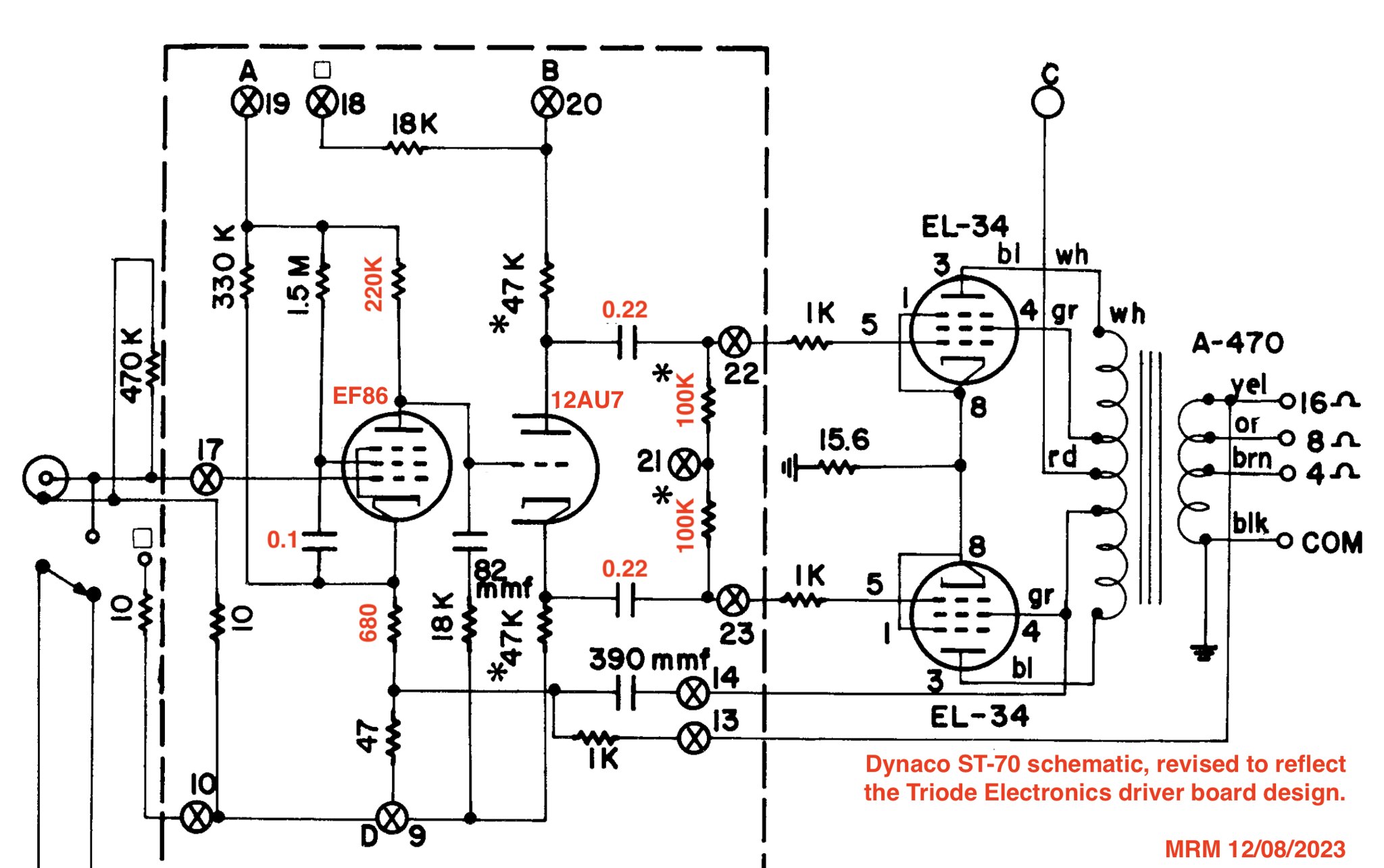
I had compared the documentation for both boards earlier in this project and they appeared to be the same design, which implements the original Dyna design with EF86 / 12AU7 tubes (described in more detail by @Salectric a little earlier in this thread). The Triode variation calls out some variations in component values while the SDS labs calls out the original Dyna values. Here are the differences I noted:
  • Decrease in the plate resistor: 270 kOhm -> 220 kOhm
  • Increase in the larger cathode resistor: 620 Ohm -> 680 Ohm
  • Decrease in the output tube grid reference resistors: 270 kOhm -> 100 kOhm
  • Increase in the coupling caps: 0.1 uF -> 0.22 uF
  • Increase in the screen decoupling cap: 0.05 uF -> 0.1 uF
The components that came with this amp were consistent with the Triode-specified values. And I have not altered any of those. The only component values I have tried altering so far were the global feedback resistors, which are out of the circuit at this time with global feedback removed.
 
I believe I have gained some insight into why the amp noise floor increases by ~3 dB in my system. It seems to be the result of noise induced in the audio interconnects...

The analog portion of my main system is simple: DAC->Passive Preamp->Amp. Everything but a couple of my amps support both balanced and unbalanced interfaces. So, I have been using unbalanced interfaces. I tried a quick test last night to see if it would help to use balanced interfaces where available and shielded twisted pair cabling for all the interfaces. I have a decent isolation transformer with balanced I/O interfaces, which I used for that last link to the amp.

DAC->Passive Preamp->Isolation Transformer->Amp

I had also tried a cheap unbalanced isolation transformer (with unbalanced cables) in the past, which didn’t help.

I made a cable for that last link which connects the isolation transformer (isolated) secondaries to the amp RCA inner and outer conductors via the cable’s twisted pair. Then I was planning to try some different variations in the cable shield connection (which cable end and whether it is tied to the isolator input shield).

The first variation I tried worked about as well as I could hope. That was with the cable shield connected to the RCA outer conductor only. The hum level from the amp in the system dropped to the same as I had measured on the bench (to the nearest dB, anyway). 82 dB / 84 dB (below the anticipated full power output of around 17 W/ch). It drops a little further when using the 4 Ohm taps for my 8 Ohm nominal speakers: 83 dB / 86 dB. I anticipate the maximum output voltage will probably drop a similar amount in that configuration. I am planning to measure that and a few other things soon…

I recently acquired a USB PicoScope and have been getting familiar with it. I already had a low-cost very basic digital scope that I bought a few years ago for automotive work. It has been fine for that and other basic usage, but I wanted something a bit more capable for audio and other projects. So far, this seems to be a great option for hobby use.

Anyway, this exercise was just to learn more about that noise symptom. I don't think I would add a transformer in the system just to reduce hum by ~3 dB, especially when it was already good enough for my preferences. This alternate interconnectivity also resulted in a 6 dB increase in the signal level received at the amp (the DAC balanced outputs are 6 dB hotter than the unbalanced outputs). That is a nice bonus, but I don’t need that right now either.
 
For anyone curious about the objective performance with the changes up to this point, here are a few graphs and measurements...

53381176189_916d9f4e92_h.jpg

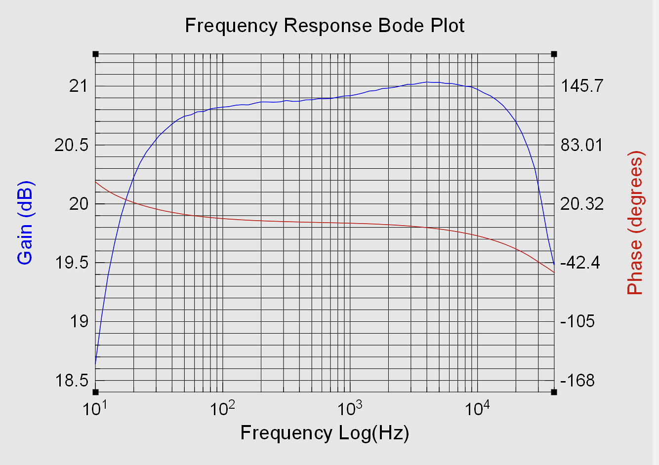
This is the frequency response with an 8 Ohm resistive load on the 8 Ohm tap. This is at about 8 Watts, but the results were pretty similar at a few other power levels I tried. Note that the entire Y scale is only about 3 dB. The gain variation between 20 Hz to 20 kHz is under +/-0.5 dB. The gain is down about 0.7 dB at 20 Hz and 0.2 dB at 20 kHz (relative to the gain at 1 kHz). Seems pretty good to me, all things considered (no global feedback in an amp originally designed to run with a good amount of it, etc).

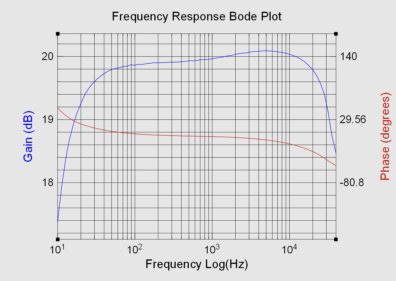
This graph was generated by the open source FRA4PicoScope app which interfaces with a PicoScope to generate Bode plots. It's very helpful. These results compare very closely to measurements I had previously made using a Tek true RMS meter (manual tone sweep at about 16 points in the passband).

53379936542_4ae8f147fb_h.jpg

And this is with an 8 Ohm resistive load on the 4 Ohm tap.

And here are some output power measurements (1 kHz, 8 Ohm resistive load):

8 Ohm output tap, 117 Volt supply voltage
15.2 Watts/ch, one channel driven​
14.3 Watts/ch, both channels driven​
4 Ohm output tap, 117 Volt supply voltage
13.0 Watts/ch, one channel driven​
12.3 Watts/ch, both channels driven​
8 Ohm output tap, 124 Volt supply voltage
17.6 Watts/ch, both channels driven​

Aside from that last power measurement, all of my measurements were made with the amp running on about 117 Volts from a variac (I settled on that voltage by adjusting the variac to 6.3 Volts at the audio tube heaters). The last measurement is with the amp plugged directly into the power outlet (no variac). That line voltage is actually the lowest I have measured in my home in recent history. I have seen it range from about 124 Volts to 126 Volts so far.

In all of the power measurement scenarios above, the limiting factor was clipping of the positive portion of the waveform. Those are the power levels just before the onset of that clipping. These output levels are a little short of what I was anticipating based on various sources, but I think it is a pretty small difference in terms of the resulting perceived loudness. Maybe a tad more power could be extracted with some fine tuning. For example, I wonder if this is happening at the driver stage and some refinement of the operating point could help (without compromising anything else). I don’t plan to explore this any further for now, but probably will eventually if I decide to stick with this amp configuration.

Note that my noise / hum measurements for this configuration earlier in this thread were relative to 17 Watts/ch. If I got the math right, the impact of this lower output level amounts to about a 1/2 dB decrease in those noise / hum numbers. Since those measurements are all rounded to the nearest dB, some of those would still be the same and some would be 1 dB worse.
 
If you want to check on where the limitations are, this is a lot easier in an amp with no loop feedback. You know what the grid bias voltage is on the output tubes, and you can simply feed a sine wave into the amp and look at what kind of waveform is available at the grids of the output tubes.
 
Thank you, @paul_b! That does sound a lot simpler than I anticipated. I’ll probably go ahead and take an initial look soon then, maybe this evening.
 
Is there a schematic for the SDS driver board? If you are getting asymetrical clipping, might need to adjust the op point of the phase splitter. Is the input stage direct coupled to the splitter? Generally you want the voltages on a split load splitter to be about 1/4 across plate resistor and 1/4 across cathode. If it is direct coupled to the voltage amp you may need to alter the op point of the pentode/triode. I didn't notice if you have posted the voltages in this thread.
John
 
Thanks for your help, @Nerdorama!

Yes, I am currently seeing asymmetrical clipping. The positive portion of the waveform is getting clipped. I drove it a bit beyond that level and did not see any clipping on the negative portion of the waveform. I have only looked at the clipping at the amp's rear speaker terminals so far, but I am now planning to take a look within the amp soon to hopefully learn more.

The input stage is indeed DC coupled to the phase splitter stage.

I have not found a schematic for the SDS driver board to date. Just the documentation linked in Post #32, which includes the board layout and component values. Based on info from @Salectric (quote below) and my own comparison of the board to the original Dyna design, I believe it is the original Dyna design, just implemented with EF86 (driver) and 12AU7 (phase splitter) tubes and some adjustments in the component values (differences listed in Post #32). One channel of the Dyna schematic is attached for quick reference.

What I always found interesting is that the 3-tube circuit is actually identical to the stock Dyna circuit; it is simply implemented with different tubes----an EF86 for each channel and a shared 12AU7 for the phase splitter compared to Dyna's 7199 which combines in a single tube a high-gain section similar to the EF86 with a lower-gain section similar to a 12AU7.

So far, I have only posted the operating voltage for the driver stage (80 Volts). I did take some measurements at the output stage when I triode strapped that stage just to see if things seemed about right, but I haven't looked at the phase splitter stage operating point. When I am in the amp next (soon), I will measure all the operating points with the current amp configuration and share them here. I'll also get some PicoScope captures along the signal path during clipping.
 

Attachments

  • Dynaco ST-70 Driver Board Schematic.png
    Dynaco ST-70 Driver Board Schematic.png
    238.3 KB · Views: 4
Last edited:
For what it's worth, I would expect the first stage plate voltage to be way, way too low when triode strapped even without looking at the schematic (the stock Dynaco ST-70 driver schematic is meaningless since you have a completely different driver board).
 
Here are some images that will hopefully more clearly illustrate what I was trying to convey earlier regarding the driver boards...

53385491610_bc0006fd50_k.jpg

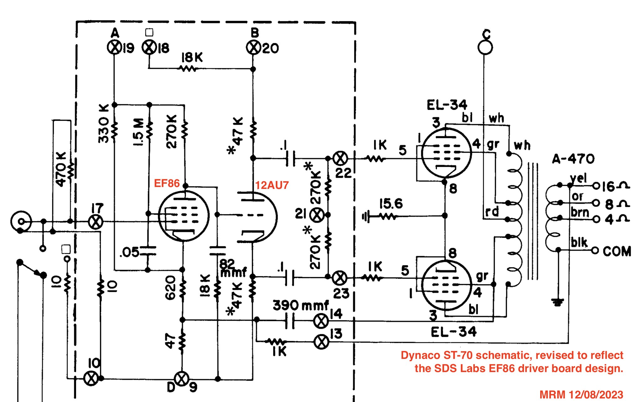
This is the Dyna schematic from my previous post, revised to reflect the SDS Labs EF86 board. Same design, just different tubes.

53385051761_e5061aa95c_k.jpg

This schematic includes further redlines to reflect the different component values that Triode Electronics calls out for their version of the driver board. Although I have the SDS Labs board, it came with the Triode Electronics component values (it was purchased through Triode a long time ago). This was my starting point.

Measured operating voltages:
(left channel, right is very similar)

EF86 Anode: 80.6 V​
EF86 Cathode: 1.614 V​
12AU7 Anode Resistor: 24.1% of supply​
12AU7 Cathode Resistor: 23.8% of supply​
EL34 #1 Grid: -34.2 V​
EL34 #2 Grid: -33.7 V​
EL34 Cathodes: 1.558 V​

So @Nerdorama, it looks like the phase splitter is not too far off (the other channel was very similar). I do appreciate your suggestion and the explanation of how to check that.

Looking at things with a 1 kHz sine wave running through the amp, the negative tip of the sine wave starts to become visibly distorted at the EF86 anode when the signal at that point is about 28 Vrms. Pushing it further, the peak continues to flatten out. Meanwhile, the positive side of the waveform looks nice, even as things are pushed a bit further.

A little elaboration on why I felt the current operating point was at least decent enough for some subjective listening (so I could decide whether I wanted to proceed further down this path). The Triode documentation I had linked previously includes a section on triode strapping the driver stage. It lists the specific steps to triode strap the EF86 and then recommends adjusting the cathode and bleeder resistors as needed to get the anode operating point in the range of 80-115 Volts. In my case, the operating point was a tad over 80 Volts, without altering any component values. I also looked at EF86 triode charts (attached) and an online load calculator that supports triode strapped EF86s (which seems to be consistent with the chart): Universal Loadline Calculator. As I am in the learning curve, I put far more weight on the Triode instructions, but the latter all seem to indicate this was at least a decent operating point to start from.

I do like what I have been hearing (at moderate levels, not pushing limits) and have decided to go ahead and continue further down this path. So, I am ready to stray from those initial component values and try to improve things further.

So, at @paul_b suggested decreasing the anode resistor to improve the operating point. The Triode instructions suggested alterating the cathode resistor and bleeder resistor to adjust the operating point. I think supply voltage is another parameter at hand...

The supply voltage for this stage has dropped around 10 Volts due to the increased current draw after the triode strapping. And as I start exploring refinement of the operating point, it seems clear the current draw is probably going to increase even further. I am thinking about reducing the dropping resistor for this power supply stage at least enough to get back to the original supply voltage (305 Volt nominal). Anyone reason not to do that? What about increasing this stage supply voltage beyond the original nominal value? This amp currently has NOS Mullard EF86s. Based on the Mullard data sheet I found online (attached), I think it shouldn't be a problem for them. Even if that is the case, I don't know if I might run into trouble if another EF86 were installed later (collected some other EF86 data sheets, trying to get an idea of what is typical).

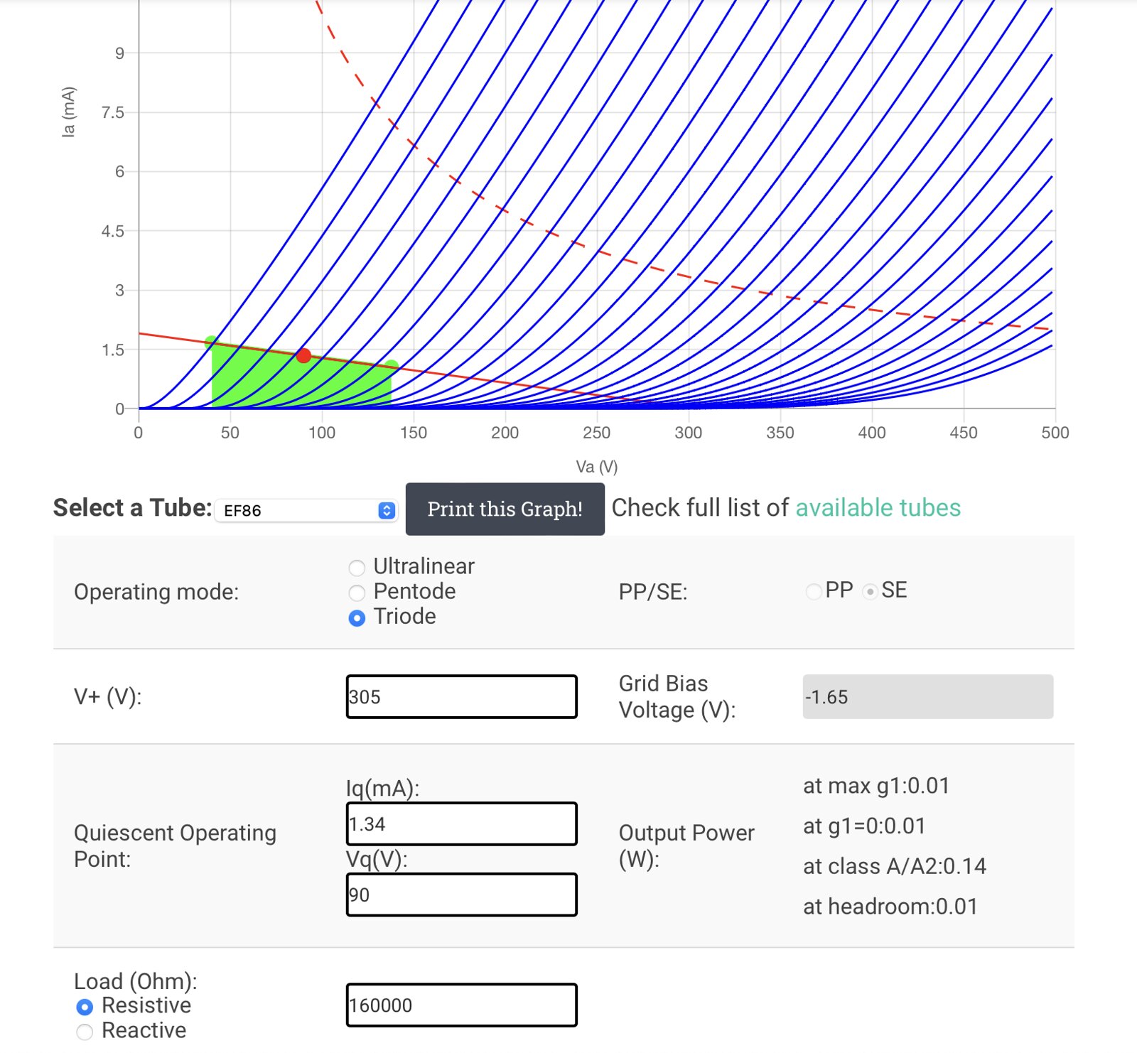
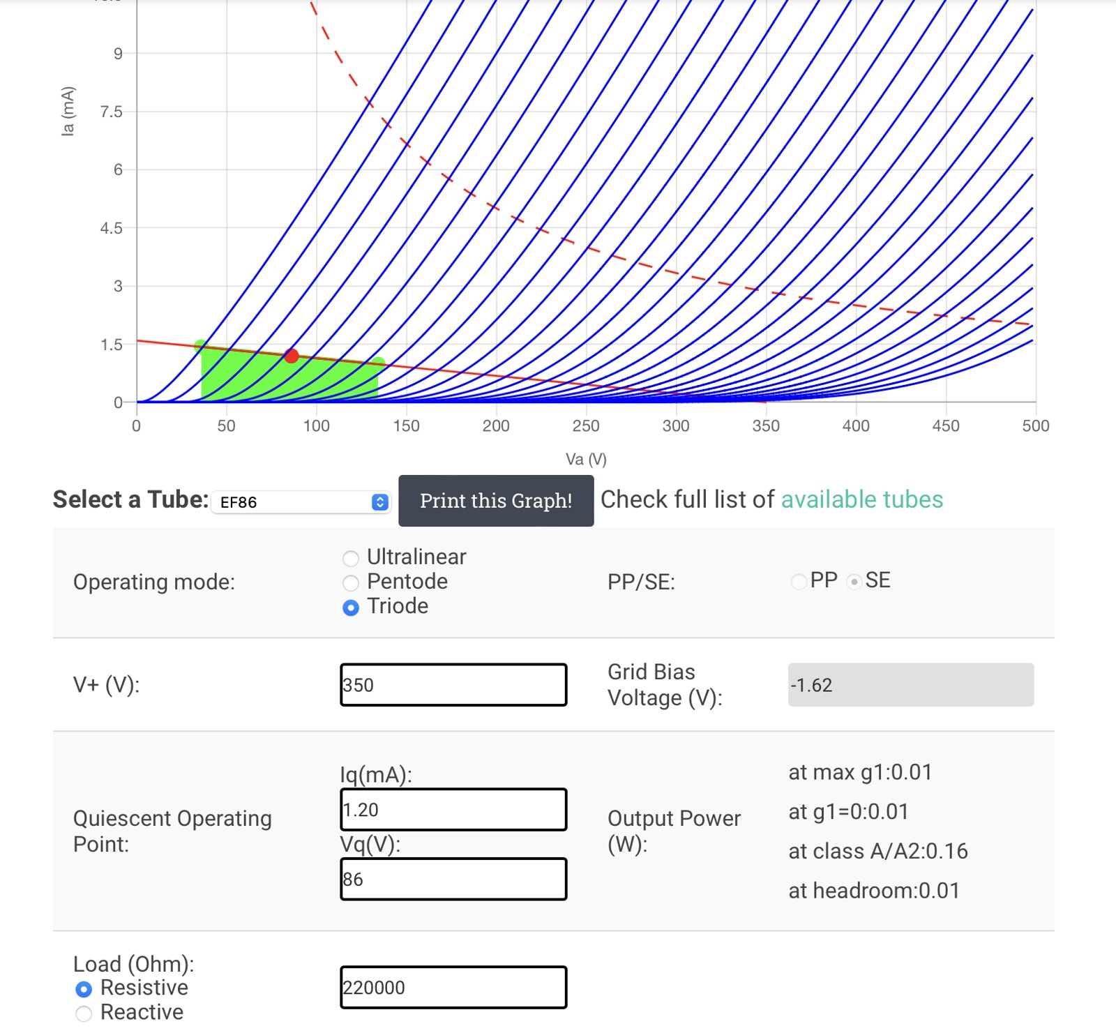
I have been doing some experimenting with different load lines in that calculator. Still learning and experimenting. Very open to feedback and suggestions. I am happy with the amount of open loop gain the amp has now, but I could sacrifice a little if needed. So that is one thing I am trying to balance in my experimenting. Note that the headroom I specified (green-shaded region) represents about a 25% increase relative to where I am hitting a limit right now. Just trying to allow a good amount of operating margin, without being too excessive (linearity on the other side of the range).

53384134282_a3e8149de1_h.jpg

Here is an example load line with V+ for this stage bumped back up to the original nominal value. The anode resistor value has been reduced to help achieve the higher headroom and maintain a similar THD. The calculator estimates THD at about 0.7% @ 14 Vrms and 1.2% @ 28 Vrms, which is similar, but slightly better, than what it estimates for the current operating point (0.8% and 1.3%) at those voltages (of course, the difference grows dramatically beyond that ~28 Vrms limit of the current operating point).

53385491625_03c5d6c8ba_h.jpg

And then here is an example of increasing that supply stage V+ to 350 Volts. This retains the original anode resistor value while maintaining similar estimated THD as the previous example (slightly better at 0.6% and 1.1%).

Does this look reasonable at least? Or off in the trees? :)
 
Back
Top