Help with Interpreting PSUD

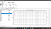
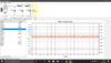
I plugged some other variables into PSUD2. Utilizing the 5R4 instead of the 5AR4 and upping the 50uf caps to the 100ufers I have. had to adjust the the first cap a little. Now, the first second rises in a smooth curve instead of a few ms of overshoot and then oscillation. Also, there is NO ripple that I can see. Are these good things or am I doing something wrong?

New
Screenshot (36).pngScreenshot (37).png

Old
 

Attachments

  • Screenshot (28).png
    Screenshot (28).png
    238.2 KB · Views: 0
  • Screenshot (31).png
    Screenshot (31).png
    260.8 KB · Views: 0
Yes, you could definitely build that an use it. Realistically your preamp tubes won't conduct as quickly as the 5R4 will, so focusing on not having a turn on spike in your power supply is not a realistic goal. If you want to see a more accurate model of your current power supply, change the constant current load to start at 2mA then step up to 33mA after a delay of 10 seconds, then model the supply for 30 seconds.
 
Last edited:
Thanks for the extra info Paul. I assume I can run some rough comparisons in PSUDII using stepped loads.

I actually would like to try a Lcrit input filter, but the power-on voltage spike prevents me doing this. So I was thinking of something like a cLcritCLC supply with the input capacitor just large enough to prevent the power-on spike. The input capacitor also provides ability to fine tune B+ voltage.

I don’t think my usual slowish B+ ramp up method of using a thermistor on the primary will help, as there little current being drawn through it when I need the voltage drop. The other options are big bleeder resistors, switchable series resistors, or timed relays... or my usual CLC arrangement. 😀
 
You can put a CL-90 in series with the primary of your power transformer and that voltage spike won't appear. Remember that when you first turn on an amp, the tube heaters are cold and draw a ton of extra current. The cold resistance of a CL-90 allows very little current when you first turn your amp on, especially when you consider the likely DCR of the primary of your power transformer. You could also put a Zener clamp across the first cap in the power supply to snub out that voltage spike. Or of course you could also realize that PSUD does a terrible job with factoring in the slow warm up of a rectifier tube in the first place, so I would suggest that the voltage spike just won't happen. (That's what I'd do!)
 
You can put a CL-90 in series with the primary of your power transformer and that voltage spike won't appear. Remember that when you first turn on an amp, the tube heaters are cold and draw a ton of extra current. The cold resistance of a CL-90 allows very little current when you first turn your amp on, especially when you consider the likely DCR of the primary of your power transformer. You could also put a Zener clamp across the first cap in the power supply to snub out that voltage spike. Or of course you could also realize that PSUD does a terrible job with factoring in the slow warm up of a rectifier tube in the first place, so I would suggest that the voltage spike just won't happen. (That's what I'd do!)

All great ideas Paul. Relevant to the OP but maybe not applicable in my next build. Was going to use SiC diodes for B+ rectification and TentLabs filament regulators (which limit current to cold filaments)...
 
Things to check in PSUD:
  1. Voltage at R1 (I would change R1 to a source of constant current and use the current your circuit draws for evaluation)
  2. Ripple at R1. You do this by zooming in on the line and looking at how much AC ripple is riding on it. You can estimate the voltage between the peak and trough of the waveform, then divide by 2.8 to get the RMS ripple.
  3. RMS current at the power transformer. This is really important since power transformers are usually rated for AC current, and this depends enormously on how your power supply is designed.
  4. IMAX of D1: Your results box should be widened, then you can see peak rectifier current. PSUD may also throw a warning for this with rectifier tubes.
For what you are doing specifically, you would want to get things setup so that what you have now is accurately represented in the simulation, then you can make those specific changes while leaving everything else alone in order to get reliable results.

-PB

This thread is a bit old and these questions hay have been answered elsewhere - apologies if I missed them. If not, hopefully someone can help.

Regarding Paul's point 3. Is the RMS current at the power transformer the RMS value shown in PSUDII (201.05mA for I(T1) in the example below)?

current_power_transformer.GIF

Regarding Paul's point 4. Should the results be run from start-up or is it the continuous operating condition that is important? Is it the Max value we are interested in (624.16m in the example above)? If using a bridge, should the value be divided for the per diode value or is that already calculated?

Thanks in advance for assistance!
 
Last edited:
You'd want to remove the step at current tap one, then check that transformer RMS current again. That is the correct field though to look at though.

For your peak diode current, that should be for the individual diodes in a bridge. A 1N4007 has something like a 15A or 20A peak rating, so this isn't the end of the world.
 
Thanks Paul. The PS shown is close to what I will be doing, but not quite - I was just using it for the exercise.

The current tap step is set for 9s, outside the range so it should not be in play. I'm using SiC diodes (not in PSUDII) and will revisit the values - I think I will purchase 5A types just to be safe - IMAX was a touch over 2A for a couple of cycles during start-up.

I will also check with my transformer winder to ensure I have it specified the HV transformer well enough. I specified the 0V-285V at the required 100mA DC current draw by the PS and asked that it be able to handle 400mA DC current draw to provide some headroom; they would do the rest. The transformer is specified at 114VA (285V*0.4A)... however, that is not correct: VA = Vac*Iac (not Idc). The transformer is currently roughly de-rated by 50%, but I'd like it closer to 100% (or even more). I also realised I had not de-rated the filament transformers.

The power transformers are not cheap: best to go back to the winder and get it right...

With a demanding day job and professional development needed, why am I doing this again? 🤔
 
Last edited:
Ok, struggling here to understand all this... I've read through this thread a handfull of times. I am trying to simulate the power supply in this thread:


Which is:

1597464102076.png

But if I was to do nothing other than swap in the Angela Universal Power Transformer. Which from what I can tell is listed as 380 - 0 - 380 and 200ma. When I go to the section that calculated the resistance of the transformer I get the following. It changes the voltage from 380 to 418... Is that correct?

1597464025482.png
 
So, it looks like I have too much voltage at both C2 and C3.

What should Iook at changing to bring those down closer to the schematic values? The resistor and the choke?

Also , the 10% regulation value for the transformer was just a gues based off what the OP did. I couldn’t find this value anywhere documented online...
 
Try decreasing the first capacitor's value. Also, I think "hot switching" that 5U4 is a bad idea. The data sheets specifically warn against it.
 
So I ran a few simulations with changing the first cap.
With the 20uf capacitor you get 490V
With a 5uf you get 480V
With a 1uf you get 450V
With a 0.22uf capacitor you get 340V

Also, are you sure about your load of 47K? Can you figure out the mA of your tubes and use the constant current option? I don't know how that is different but Paul B had me do that.
 
Delete C1 and change the RC network into the LC network you have now. Change the value of L1 to get the appropriate B+ value. I suggest just opening Hammond's choke page and looking at the chokes that are under 1H to use in this spot. This will also decrease AC current through the power transformer which is an added benefit.

The step of deleting C1 is the method required for PSUD to simulate a choke input filter, which it is otherwise not all that willing to do.
 
So I ran a few simulations with changing the first cap.
With the 20uf capacitor you get 490V
With a 5uf you get 480V
With a 1uf you get 450V
With a 0.22uf capacitor you get 340V

Also, are you sure about your load of 47K? Can you figure out the mA of your tubes and use the constant current option? I don't know how that is different but Paul B had me do that.
So, first question, do I change the voltage for the transformer to the amount given when calculating the impedance or change it back to the manufacturer value? In this case, manufacture value is 380 - 0 - 380, PSUD wants to change it to 418.

I looked at your screenshots and it looks like you accepted the impedance value but changed the voltage value back...?

I changed C2 and C3 to 50uf since those are much easier values to find. Also, this may be a silly question but wouldn't the easiest way to knock down the voltage be with resistors?

Our goals are 465V at C2 and 435V at C3 based on the schematic...

This gets pretty close, no?

1597510778125.png
 
Delete C1 and change the RC network into the LC network you have now. Change the value of L1 to get the appropriate B+ value. I suggest just opening Hammond's choke page and looking at the chokes that are under 1H to use in this spot. This will also decrease AC current through the power transformer which is an added benefit.

The step of deleting C1 is the method required for PSUD to simulate a choke input filter, which it is otherwise not all that willing to do.

Ok. I'll give this a shot and report back. Thanks Paul!
 
When putting in the transformer info, give the manufacturer's rated voltage and current, then make an educated guess about regulation. Generally 10% is close enough. That will auto-populate some new values to make your simulation more accurate.

To drop voltage, you could use a resistor, but a choke will improve regulation and lighten the load on the power transformer. Try, for instance, the 0.5H/30 ohm Hammond as a choke input filter and see how things look.
 
Back
Top