I robbed a scope...Where did you get the extension? I'm looking for some good ones.
You are using an out of date browser. It may not display this or other websites correctly.
You should upgrade or use an alternative browser.
You should upgrade or use an alternative browser.
The JE Labs/ Angela SE 2A3 amplifier, revisited
- Thread starter Redboy
- Start date
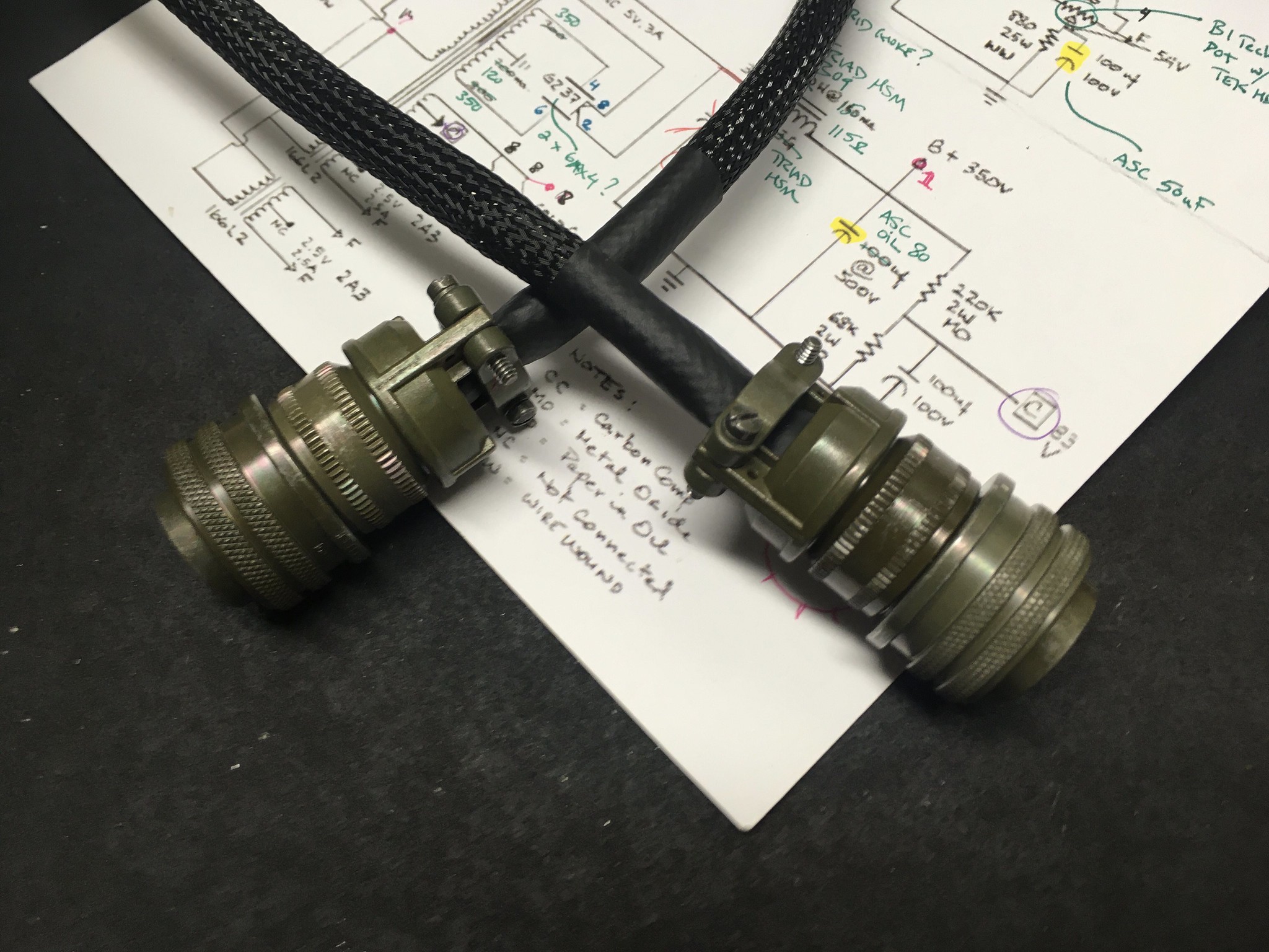
As Bogey said to Ingrid BergmanRemind me not to build anything with an Amphenol umbilical again. These things are an exercise in not fun.
We'll always have Molex

That looks vaguely like a garden hose.The finished umbilical...
")
Could you provide a little more details around those big Bosch MKP caps there, Nate?
Each end has ten solder points, which isn’t difficult in and of itself. But each individual wire is treated with a piece of heat shrink over those solder points, metal braid over the whole bundle, tech flex over that, and a larger heat shrink over each end. All of these things and the connector parts need to be installed on the bundle in proper (reverse) order before soldering the second end. Then you solder the correct wires to their respective points, slide the (previously installed) heat shrink over the solder points, slide the (previously installed) braid over the bundle, then the (previously installed) tech flex and the (previously installed) finishing heat shrink. Heat it in place, then slide the (previously installed) connector ends down and affix them properly.I still don't understand what was so difficult about the umbilical construction.
Did you miss anything, or put something on in the wrong order? Uh oh, now you get to re-do it all and try again!

Yeah, they kinda suck.
")
I had 'em handy...Could you provide a little more details around those big Bosch MKP caps there, Nate?
I don't remember where or when I got them, but they're supposed to be pretty nice and I would prefer not to use electrolytics for some silly reason.
Each end has ten solder points, which isn’t difficult in and of itself. But each individual wire is treated with a piece of heat shrink over those solder points, metal braid over the whole bundle, tech flex over that, and a larger heat shrink over each end. All of these things and the connector parts need to be installed on the bundle in proper (reverse) order before soldering the second end. Then you solder the correct wires to their respective points, slide the (previously installed) heat shrink over the solder points, slide the (previously installed) braid over the bundle, then the (previously installed) tech flex and the (previously installed) finishing heat shrink. Heat it in place, then slide the (previously installed) connector ends down and affix them properly.
Did you miss anything, or put something on in the wrong order? Uh oh, now you get to re-do it all and try again!
Yeah, they kinda suck.
I've had to redo plenty of them, and it is a super pita.... I try to use the 5 pin connectors because it's so much easier to solder and slip heat shrink on them. 18awg seems to be about the biggest you can reasonably use too. I use 16awg plenty, but it's much more of a pain to fit into the solder cup/pad.
Yeah, no ‘lytics in this circuit at all except for a couple of small bypass caps on the input tube.The cathode bypass caps and the electrolytic cap where the output transformer connects are very much in the signal path.
Oh.
It's an integrated amp.

It's an integrated amp.
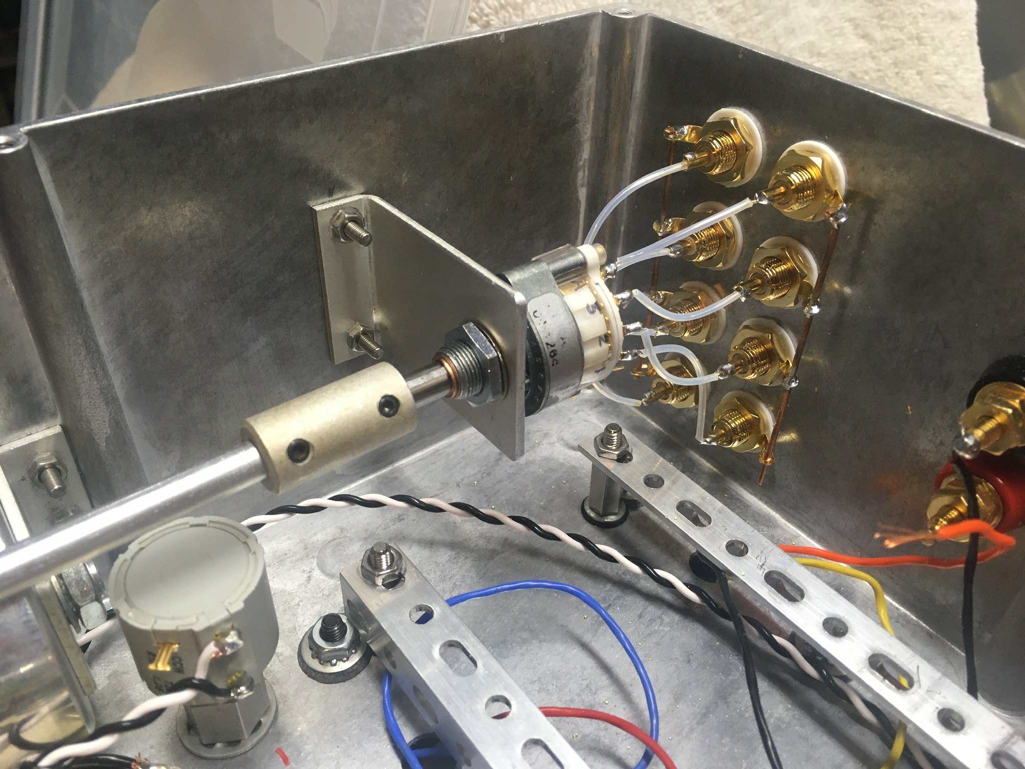
No way I could do that by hand! It's all about careful layout, then center punch, then a tiny pilot hole... and then the stepped bit in a drill press.I admire anyone who can drill holes for RCA jacks that straight by hand!
My first attempt at cutting holes (by hand) in an amp chassis was the very same day I bought my first drill press!
Nice job. I really like the two chassis design , beautiful!
Would you mind let me know where I can buy this big Hammond Case, and the small angle Aluminum Bar ?
Would you mind let me know where I can buy this big Hammond Case, and the small angle Aluminum Bar ?
Similar threads
- Replies
- 12
- Views
- 1K